Charging apparatus

a charging device and charging technology, applied in the direction of electric devices, battery/fuel cell control arrangements, electric devices, etc., can solve the problems of inability to solve the problem of improper charging operation and inability to charge properly

Inactive Publication Date: 2016-06-16
TOYOTA JIDOSHA KK
View PDF1 Cites 10 Cited by
  • Summary
  • Abstract
  • Description
  • Claims
  • Application Information

AI Technical Summary

Benefits of technology

[0028]According to the charging apparatus of the present invention, as described above, the high-output load mounted on the vehicle can be appropriately operated.

Problems solved by technology

In the technology described in Japanese Patent Application Laid Open No. 2011-176958, when the MOS-FET is in a cutoff state, if a load (or an electrical device) that requires power supply from two storage batteries for stable operation, such as, for example, an electric active stabilizer, is operated, there is a possibility that the load is not appropriately operated because the power supply is performed only from the lithium storage battery, which is technically problematic.
In the technologies described in Japanese Patent Application Laid Open No. 2011-178384 and Japanese Patent Application Laid Open No. 2007-122882, the technical problem cannot be solved.

Method used


Image

  • Charging apparatus
  • Charging apparatus
  • Charging apparatus

Examples


modified example

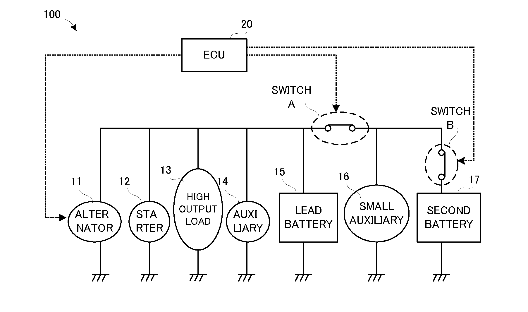
[0093]Next, a modified example of the charging apparatus 100 according to the embodiment will be explained with reference to FIG. 6. FIG. 6 is a diagram illustrating one example of respective voltage characteristic lines of the lead battery, the nickel hydrogen battery, and a lithium ion battery.

[0094]In the described above, the second battery 17 (refer to FIG. 1) is the nickel hydrogen battery. Even if the second battery 17 is a lithium ion battery, the charge control process according to the embodiment described above can be applied.

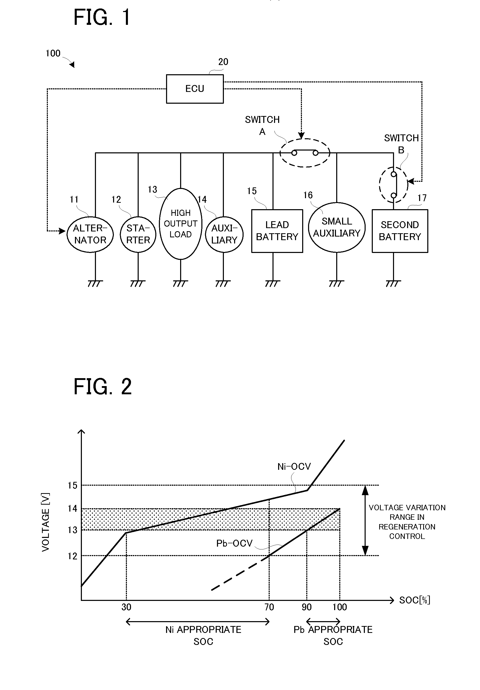
[0095]For example, as illustrated in FIG. 6, an appropriate SOC range of the lithium ion battery is SOC 30% to 70%. Open circuit voltage range corresponding to the appropriate SOC range of the lithium ion battery is 12.8V to 14V (refer to “Li-OCV” in FIG. 6). Therefore, an overlap range between the open circuit voltage range corresponding to the appropriate SOC range of the lead battery 15 and the open circuit voltage range corresponding to the appropr...


PUM


Abstract

A charging apparatus is mounted on a vehicle having a plurality of batteries and a power generating device. The charging apparatus is provided with a controller (i) configured to obtain power accumulation ratios of the plurality of batteries, (ii) configured to determine whether or not each of obtained power accumulation ratios is in an appropriate range corresponding to each of the plurality of batteries, and (iii) configured to control the power generating device so that generated voltage of the power generating device is in an overlap range, if it is determined that power accumulation ratio of one battery of the plurality of batteries is greater than an upper limit of the appropriate range of the one of battery and if the power generating device performs the power regeneration upon deceleration of the vehicle.

Description

CROSS-REFERENCE TO RELATED APPLICATIONS[0001]This application is based upon and claims the benefit of priority of the prior Japanese Patent Application No. 2014-251901, file on Dec. 12, 2014, the entire contents of which are incorporated herein by reference.BACKGROUND OF THE INVENTION[0002]1. Field of the Invention[0003]The present invention relates to a charging apparatus mounted on a vehicle such as, for example, an automobile.[0004]2. Description of the Related Art[0005]As this type of apparatus, for example, there is proposed an apparatus having such a configuration that a lead storage battery, a lithium storage battery, a generator, and a load are electrically connected in parallel with each other, the apparatus being provided with: a MOS-FET configured to switch between conduction and blockage between (i) the generator and the lead storage battery and (ii) the lithium storage battery and the load; and a relay electrically connected between the MOS-FET and the lithium storage b...

Claims


Application Information

Patent Timeline
Patent Type & Authority Applications(United States)
IPC IPC(8): B60L11/18
CPCB60L11/1805B60L11/1814H02J7/1423B60L7/10B60L2240/80Y02T10/70B60L50/10B60L58/13B60L58/20B60L58/15Y02T10/7072
Inventor SUZUKI, TAKEAKIMIYASHITA, MICHIHIROESHIMA, KAZUHITONATE, HIROSHIHORITAKE, SUNAO
Owner TOYOTA JIDOSHA KK
Why Eureka
Try Eureka