
Apparatus and method for manufacturing group 13 nitride crystal

a technology of nitride crystal and apparatus, which is applied in the direction of crystal growth process, polycrystalline material growth, pressurized chemical process, etc., can solve the problems of deterioration in the quality of the crystal to be obtained, the concentration distribution in the mixed melt is not uniform, etc., and achieves high quality, increased crystal growth rate, and large size

Inactive Publication Date: 2016-06-16
RICOH KK
View PDF5 Cites 0 Cited by
  • Summary
  • Abstract
  • Description
  • Claims
  • Application Information

AI Technical Summary

Benefits of technology

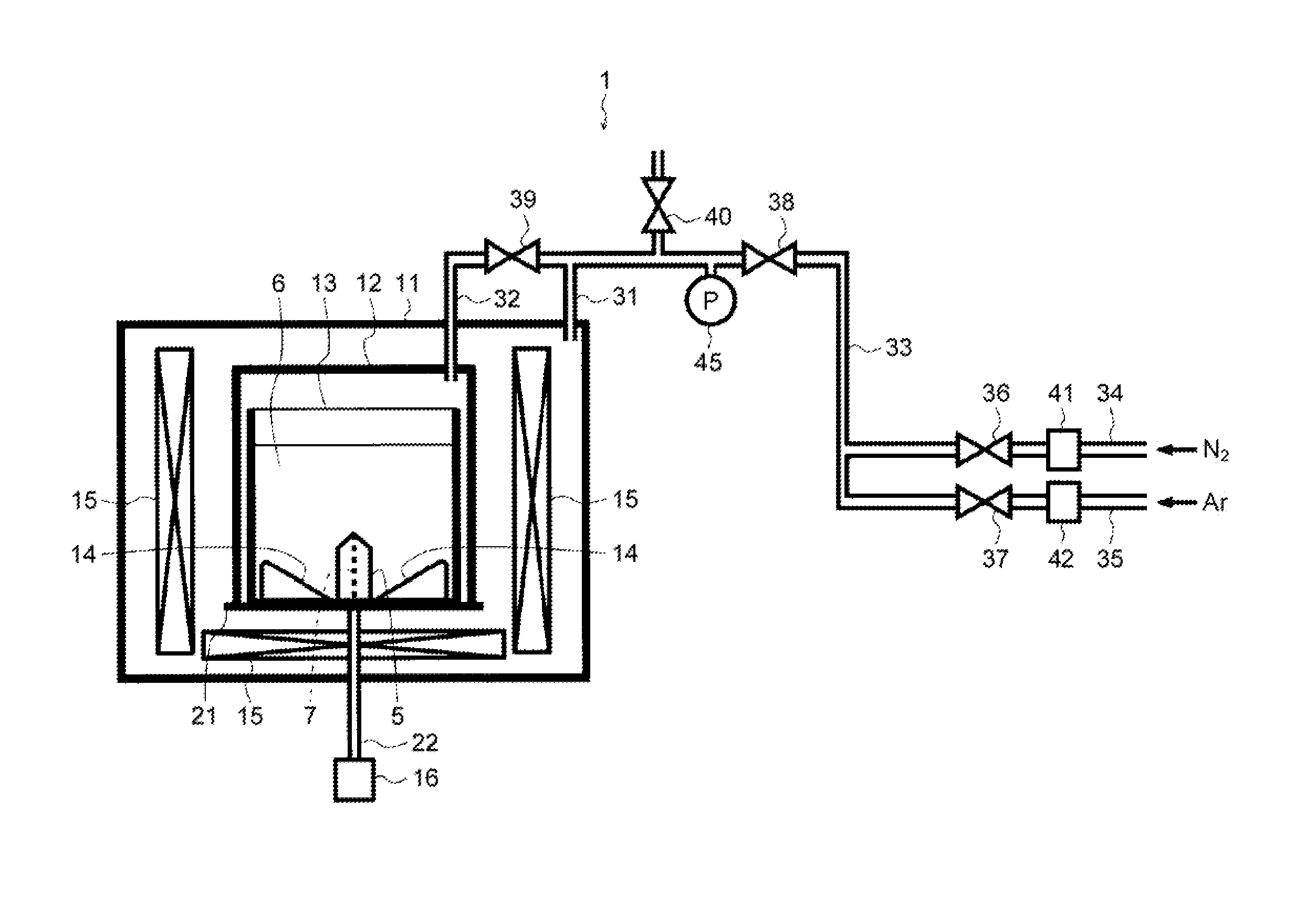
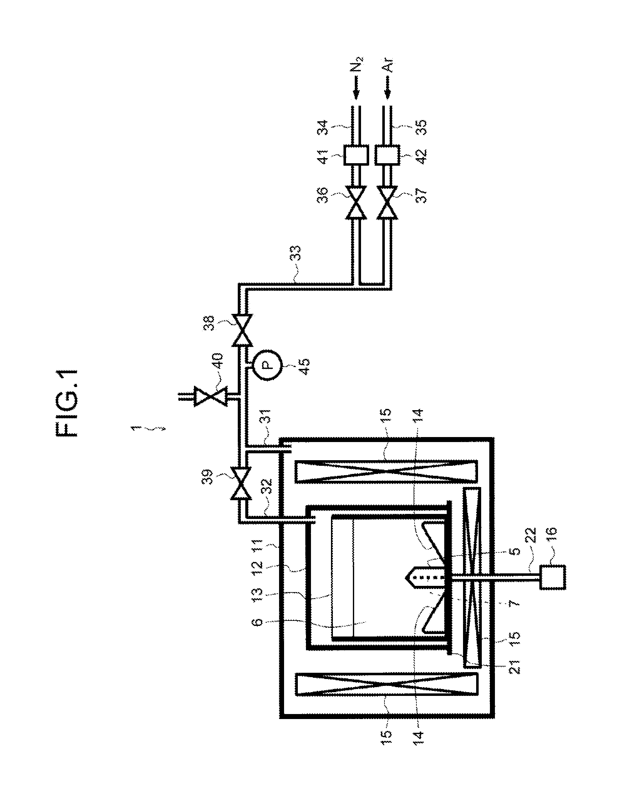
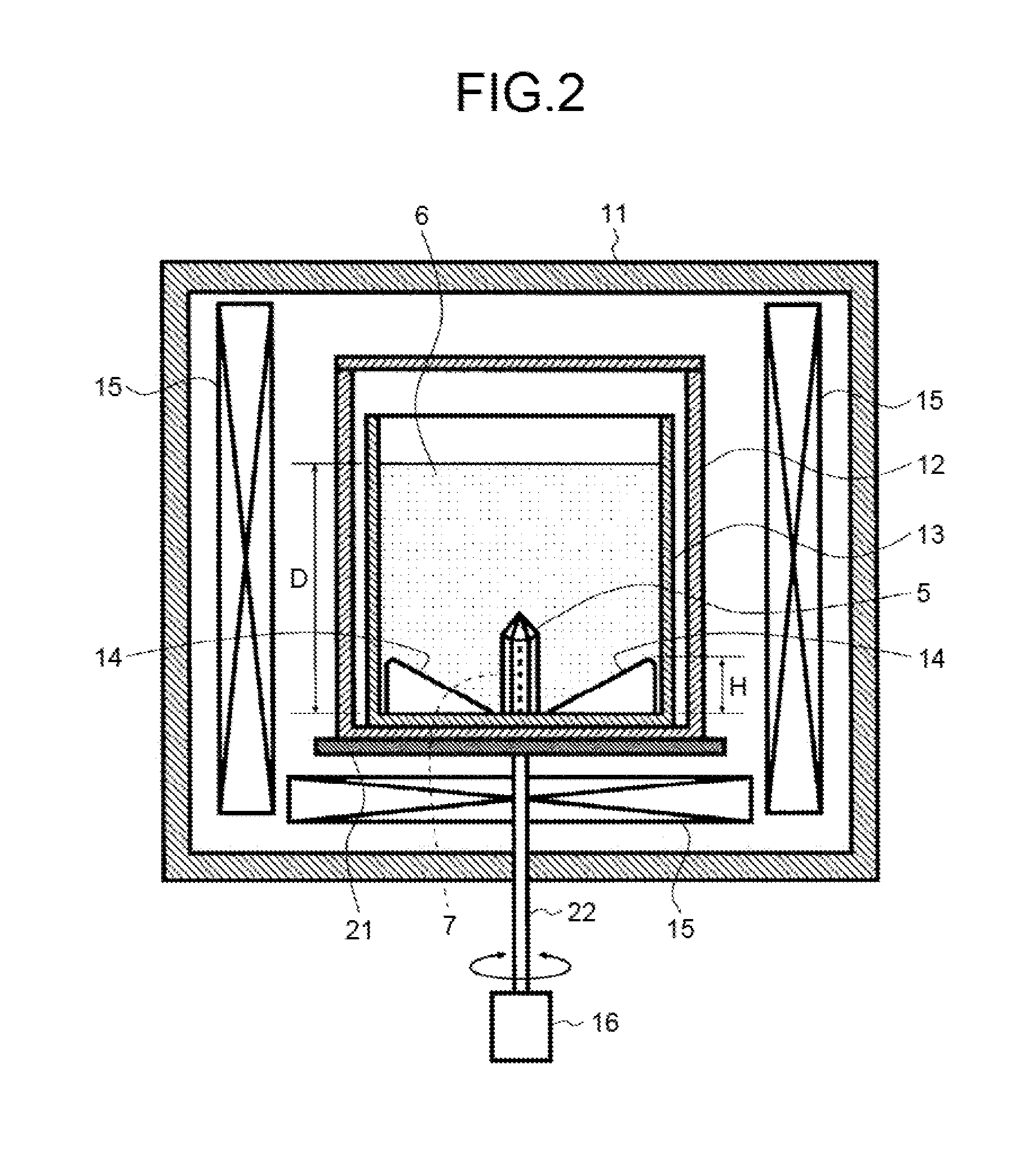
The present invention addresses the problem of obtaining high-quality, large-sized group 13 nitride single crystals using conventional methods such as shaking and stirring. These methods may improve the crystal growth rate but can compromise the quality of the obtained crystal. The inventors found that maintaining a favorable stirred condition over a long time is necessary to obtain high-quality, large-sized single crystals. The present invention provides an apparatus for manufacturing group 13 nitride crystals using a flux method that includes a reaction vessel, rotational mechanism, and structure for stirring the mixed melt. The structure is designed such that a portion close to the inner wall of the reaction vessel has a higher height than a portion close to the center of the reaction vessel. This design improves the quality, consistency, and size of the obtained crystals.

Problems solved by technology

In the flux method, the source gas dissolves into the mixed melt from the vapor-liquid interface between the mixed melt and the source gas, and the concentration of a solute (nitrogen) in the mixed melt tends to increase near the vapor-liquid interface, which is likely to cause solute concentration distribution in the mixed melt.
Such solute concentration distribution causes deterioration in the quality of a crystal to be obtained.

Method used


Image

  • Apparatus and method for manufacturing group 13 nitride crystal
  • Apparatus and method for manufacturing group 13 nitride crystal
  • Apparatus and method for manufacturing group 13 nitride crystal

Examples


example 1

[0056]In the present example, a gallium nitride (GaN) crystal was grown as the group 13 nitride crystal 5 using the baffle 14A illustrated in FIG. 3.

[0057]First, in the reaction vessel 13 made of alumina in a glove box with a high-purity Ar atmosphere, four baffles 14A made of alumina having the shape illustrated in FIG. 3 were arranged point-symmetrically with respect to the central axis 70 of the reaction vessel 13. With regard to the planar arrangement, the four baffles 14A were arranged with 90°-symmetry with the central axis 70 as a center when viewing the reaction vessel 13 from above. The baffle 14A is a triangular plate-shaped member having the height H of 35 mm, and the contact face (the lower face 57) with the reaction vessel 13 and the contact face (the side faces 55, the upper face 56, and the outer side face 58) with the mixed melt 6 are all planes. In other words, the sections of the edges of the faces are nearly the right angle.

[0058]Next, sodium (Na) liquefied by hea...

example 2

[0068]In the present example, a gallium nitride (GaN) crystal was grown as the group 13 nitride crystal 5 using the baffles 14B illustrated in FIG. 4.

[0069]First, in the reaction vessel 13 made of alumina in a glove box with a high-purity Ar atmosphere, four baffles 14B made of alumina illustrated in FIG. 4 were arranged point-symmetrically with respect to the central axis 70 of the reaction vessel 13. With regard to the planar arrangement, the four baffles 14B were arranged with 90°-symmetry with the central axis 70 as center when viewing the reaction vessel 13 from above. Each of the baffles 14B has the height H of the peripheral portion 52 of 35 mm and has the chamfered portions 59 on the edge of the triangle. All the faces 55, 56, 57, 58 of the baffle 14B are planes.

[0070]Next, sodium (Na) liquefied by heating was put into the reaction vessel 13 as the mixed melt 6. After the sodium solidified, gallium (Ga) and carbon were put thereinto. In the present example, the molar ratio b...

example 3

[0078]In the present example, a gallium nitride (GaN) crystal was grown as the group 13 nitride crystal 5 using the baffles 14C illustrated in FIG. 5.

[0079]First, in the reaction vessel 13 made of alumina in a glove box with a high-purity Ar atmosphere, four baffles 14C made of alumina having the shape illustrated in FIG. 5 were arranged point-symmetrically with respect to the central axis 70 of the reaction vessel 13. With regard to the planar arrangement, the four baffles 14C were arranged with 90°-symmetry with the central axis 70 as center when viewing the reaction vessel 13 from above. Each of the baffles 14C has the height H of the peripheral portion 52 of 35 mm and has the curved face 60 as the upper face 56, the outer side face 58, and the edges (sides) of the triangular shape.

[0080]Next, sodium (Na) liquefied by heating was put into the reaction vessel 13 as the mixed melt 6. After the sodium solidified, gallium (Ga) and carbon were put thereinto. In the present example, th...


PUM

PropertyMeasurementUnit
molar ratioaaaaaaaaaa
angleaaaaaaaaaa
angleaaaaaaaaaa

Abstract

An apparatus is used for manufacturing a group 13 nitride crystal by using a flux method. The apparatus includes a reaction vessel, a rotational mechanism, and a structure. The reaction vessel contains a mixed melt and a seed crystal placed in the mixed melt. The mixed melt contains an alkali metal or an alkali-earth metal and a group 13 element. The rotational mechanism rotates the reaction vessel. The structure is provided inside the reaction vessel for stirring the mixed melt and is constructed such that a height of a first portion of the structure close to an inner wall of the reaction vessel is higher than a height of a second portion of the structure close to a center of the reaction vessel.

Description

TECHNICAL FIELD[0001]The present invention relates to an apparatus and a method for manufacturing a group 13 nitride crystal, and in particular, to a technology for manufacturing a group 13 nitride single crystal such as gallium nitride and aluminum nitride.BACKGROUND ART[0002]A flux method is known as a method for manufacturing group 13 nitride crystals. In the flux method, a source gas such as a nitrogen gas is dissolved in a mixed melt (flux) containing an alkali metal or an alkali-earth metal and a group 13 metal to form a supersaturated state. In the mixed melt, a group 13 nitride crystal is grown by growing a spontaneous nucleus or by using a seed crystal as a nucleus.[0003]In the flux method, the source gas dissolves into the mixed melt from the vapor-liquid interface between the mixed melt and the source gas, and the concentration of a solute (nitrogen) in the mixed melt tends to increase near the vapor-liquid interface, which is likely to cause solute concentration distribu...

Claims


Application Information

Patent Timeline
Patent Type & Authority Applications(United States)
IPC IPC(8): C30B9/00C30B29/40
CPCC30B29/406C30B9/00C30B19/06C30B9/10C30B19/02C30B35/002
Inventor SATOH, TAKASHIHAYASHI, MASAHIROSARAYAMA, SEIJIKATO, YOSHIKAZUMORI, YUSUKE
Owner RICOH KK
Learn More