Electrospinning apparatus and method for producing multi-dimensional structures and core-sheath yarns

a technology of electrospun and coresheath yarn, which is applied in the field of electrospun, can solve the problems of poor mechanical properties, non-woven or aligned two-dimensional electrospun membranes lacking desirable characteristics such as porosity and strength, and achieves the effect of achieving non-woven or aligned two-dimensional electrospun membranes that are lacking in several applications and lack the desired characteristics of porosity and strength

Active Publication Date: 2016-06-16
AMRITA VISHWA VIDYAPEETHAM +1
View PDF0 Cites 8 Cited by
  • Summary
  • Abstract
  • Description
  • Claims
  • Application Information

AI Technical Summary

Benefits of technology

[0010]A method of producing a two or three-dimensional scaffold by electrospinning is disclosed, comprising loading at least one fiber source at a first potential with solution formulation or melt and placing a rotatable collector unit adjacent the fiber source at a second potential. The collector unit is configured comprising a plurality of electrodes connected at one end and mounted with tines at the other end to form an open structure. Fiber from the source is then deposited into the collector using the potential difference to generate a scaffold. In one aspect of the method the open structure is configured to have diameter in the range 10-20 cm to generate a three-dimensional scaffold. In another aspect the open structure is configured to have diameter in the range 1-10 cm to generate a two-dimensional scaffold. In one aspect of the method, the density of the solution or melt and the diameter of collector are minimized so that a diameter of a whipping region of the fiber exceeds a diameter of the collector to generate a two-dimensional scaffold. In another aspect of the method, the density of the solution or melt and the diameter of the collector are increased such that the whipping region is minimized and the scaffold is contained within the collector to generate a three-dimensional scaffold.

Problems solved by technology

However, a major limitation of traditional electrospun scaffolds is that they have tightly packed layers of fibers with a superficially porous network and poor mechanical properties.
However, these known methods yield either non-woven or aligned two dimensional electrospun membranes lacking desirable characteristics such as porosity and strength towards several applications.

Method used


Image

  • Electrospinning apparatus and method for producing multi-dimensional structures and core-sheath yarns
  • Electrospinning apparatus and method for producing multi-dimensional structures and core-sheath yarns
  • Electrospinning apparatus and method for producing multi-dimensional structures and core-sheath yarns

Examples


example 1

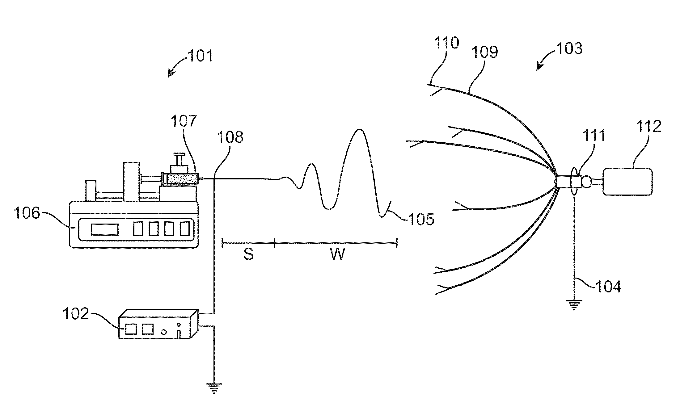
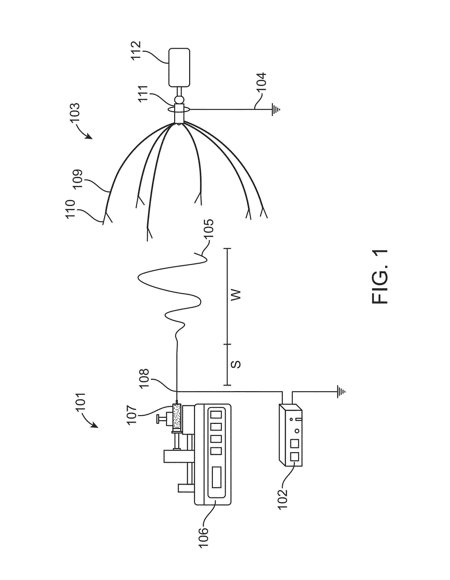
[0041]Example 1 illustrates fabrication of two dimensional non-woven mats using the above electrospinning setup. The polymeric solution was loaded in a syringe connected to a metallic spinneret which was placed at 180° relative to the axis of the collector. The spinneret was maintained at a positive potential (7-15 kV) and the collector was grounded. The rotation speed of the motor attached to the collector was set to 100 rpm so as to maintain a uniform electric field at each circumferential plane of the collector. To obtain 2-D electrospun mats as shown in FIGS. 7A and 7B, the diameter of the collector was adjusted to be less than 10 cm. If mass of polymeric solution (inertia) is low or if the diameter of collector is less than 10 cm, the whipping region takes over the stable region and if the whipping region covers a larger area than the diameter of the collector, fibers will deposit in the form of a mat as shown in FIG. 7A. Other operational parameters such as flow rate, voltage,...

example 2

[0042]Example 2 illustrates fabrication of three dimensional fluffy scaffolds using the above electrospinning setup. Two syringes loaded with polymeric solution were applied positive and negative polarity (7-15 kV) respectively, and aligned such that their spinnerets were set at ˜90° relative to each other and at 45° to the axis of the collector as shown in FIG. 3B. The collector was grounded and the rotation speed of the motor attached to the collector was set to 100 rpm so as to maintain a uniform electric field at each circumferential plane of the collector.

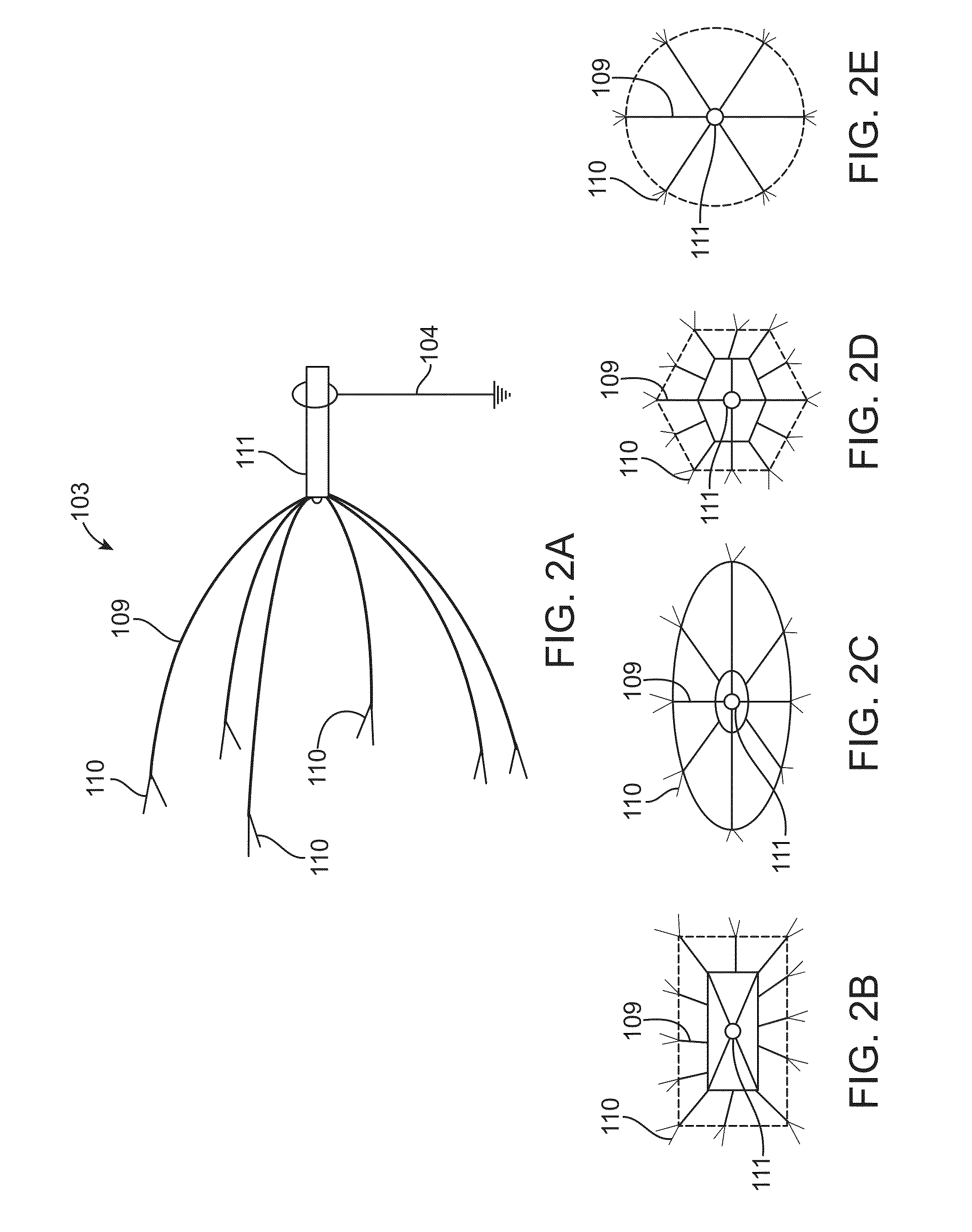
[0043]To obtain 3-D fluffy fibers, the diameter of the hemispherical collector was adjusted from 12 to 15 cm. Other operational parameters such as flow rate, voltage, tip-target distance and concentration of the polymeric solution were optimized by changing the parameters independently so as to generate fibrous scaffolds with fibers of optimal diameter. FIG. 8A shows the optical image of three dimensional electrospun fluffy PL...

example 3

[0044]In Example 3, using the same electrospinning setup, 1-D continuous yarns were obtained from the 3-D fluffy scaffold deposited within the collector set to a diameter of 12-15 cm. The spinneret in this case was positioned at an angle of 45° with respect to the axis of the hemispherical collector. Such an arrangement would facilitate yarn withdrawal from the collector. After subsequent deposition of fibers onto the needles, a guide wire was introduced to withdraw the fibrous mass, resulting in the formation of a cone near the mouth of the collector. Additionally, the rotation of the collector imparts a twist to the fibers, which in turn bundles them together to form a stable interlocked yarn. These yarns were then drawn towards a rotating mandrel whose speed was synchronized with that of the rotating collector. The variation of individual fiber as well as yarn diameters with parameters such as voltage, concentration of the polymeric solution, flow rate, collector rotation and upt...


PUM

PropertyMeasurementUnit
diameteraaaaaaaaaa
diameteraaaaaaaaaa
diametersaaaaaaaaaa

Abstract

Electrospinning apparatus and method for producing multi-dimensional structures such as one-dimensional continuous yarns, two-dimensional mats and three-dimensional cotton-like fluffy scaffolds is disclosed. Further, electrospinning apparatus and method with single collector geometry for producing multi-dimensional structures and core-sheath yarns are disclosed.

Description

CROSS-REFERENCES TO RELATED APPLICATIONS[0001]This application claims priority to Indian patent application No. 3131 / CHE / 2014, filed on 27 Jun. 2014, the full disclosure of which is incorporated herein by reference.FIELD OF THE INVENTION[0002]The present invention is related to electrospinning apparatus and method for producing multi-dimensional structures such as one-dimensional continuous yarns, two-dimensional mats and three-dimensional cotton-like fluffy scaffolds.DESCRIPTION OF THE RELATED ART[0003]With foregoing technical advancement, electrospinning technology is widely applied as it is a simple and effective process for producing nano or micro-scale fiber materials. The fiber materials are widely used as biomedical materials, for tissue engineering, as photoelectric materials, filtering materials, sensors and the like. Generally, this technology involves formation of a fine jet of a solution or melt of a polymer or other material in a high-voltage electric field. The jet is ...

Claims


Application Information

Patent Timeline
Patent Type & Authority Applications(United States)
IPC IPC(8): D01D5/00D01D4/02D01D11/06
CPCD01D5/0069D01D11/06D10B2403/033D10B2331/041D10B2401/12D01D4/02D01D5/0076D01D5/0084D02G3/36D02G3/00
Inventor MENON, DEEPTHYJOSEPH, JOHNNAIR, SHANTIKUMAR
Owner AMRITA VISHWA VIDYAPEETHAM
Why Eureka
Try Eureka