Touch window

a technology of touch window and metal plate, applied in the field of touch window, can solve the problems of complex processes, limited fine-pattern formation schemes, and exposed schemes, and achieve the effects of improving the pattern precision of wires, and improving the filling rate of metallic materials

Active Publication Date: 2016-06-16
LG INNOTEK CO LTD
View PDF5 Cites 4 Cited by
  • Summary
  • Abstract
  • Description
  • Claims
  • Application Information

AI Technical Summary

Benefits of technology

[0008]As described above, according to one embodiment, the wire of the touch window includes the dummy part. The pattern precision of the wire can be improved due to the dummy part. In particular, when the wire is formed through a scheme of filling a metallic material, the filling rate of the metallic material can be improved For example, when the wire is formed through a filling scheme based on the squeegee, the squeegee passes the wire pattern while filling the metallic material in the wire pattern. In this case, due to the dummy part, the squeegee can be prevented from being dropped into the first pattern. In addition, the dummy part serves as a step, so that the time at which the squeegee passes is prolonged, and the time, at which the metallic material is filled, is increased, so that the filling rate of the metallic material can be improved. Therefore, the wire pattern may be prevented from being disconnected, so that the electrical characteristic of the touch window can be improved.
[0009]Conventionally, when the metallic material is filled, the squeegee may be dropped into the wire pattern, so that the process efficiency may be degraded. In addition, when the pattern to be filled with the metallic material is perpendicular to the movement direction of the squeegee, the filling material may not be uniformly filled into the pattern. According to the present embodiment, the above problem can be solved due to the dummy part.
[0010]Meanwhile, according to another embodiment, the first and second wire parts inclined from the edge of the substrate are provided. Accordingly, the filling rate of the metallic material can be improved. In detail, when the wire is formed through the scheme of filling a metallic material by using the squeegee, a pattern perpendicular to the movement direction of the squeegee is not allowed, so that the metallic material can be uniformly filled.
[0011]However, according to the present embodiment, since an additional cutting work of the substrate is not required, the material efficiency can be improved, so that the productivity can be improved.

Problems solved by technology

However, according to the photolithography scheme, processes are complicated in that the photoresist must be laminated, exposed, and developed.
Accordingly, the schemes have the limitation in forming fine-patterns.
Meanwhile, according to a scheme of filling a material in the pattern, the pattern is not filled with the material in uniform amount, so that the filling failure may be caused.

Method used


Image

  • Touch window
  • Touch window
  • Touch window

Examples


Embodiment Construction

[0034]In the following description of the embodiments, it will be understood that, when a layer (or film), a region, a pattern, or a structure is referred to as being on or under another substrate, another layer (or film), another region, another pad, or another pattern, it can be directly or indirectly on the other substrate, layer (or film), region, pad, or pattern, or one or more intervening layers may also be present. Such a position of the layer has been described with reference to the drawings.

[0035]The thickness and size of each layer (or film), each region, or each structure shown in the drawings may be exaggerated, omitted or schematically drawn for the purpose of convenience or clarity. In addition, the size of each of the elements does not utterly reflect an actual size.

[0036]Hereinafter, the embodiments will be described with reference to the accompanying drawings.

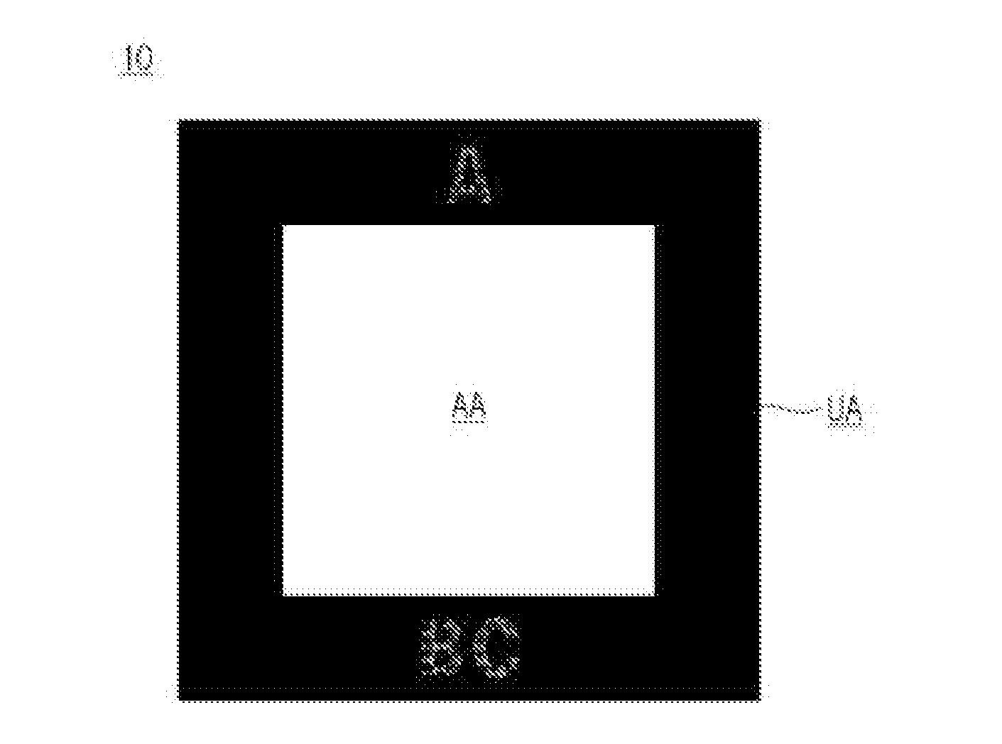
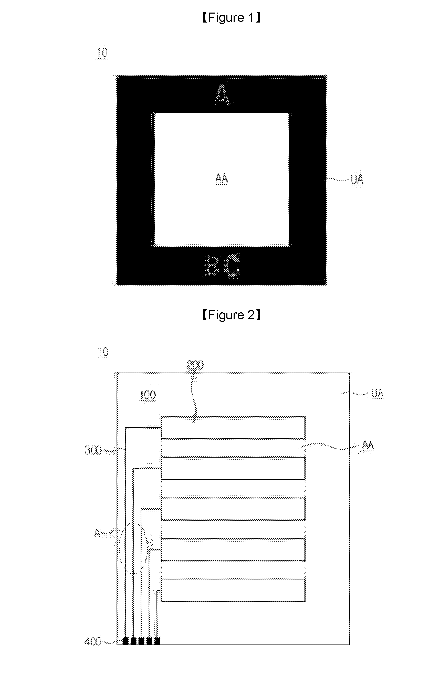
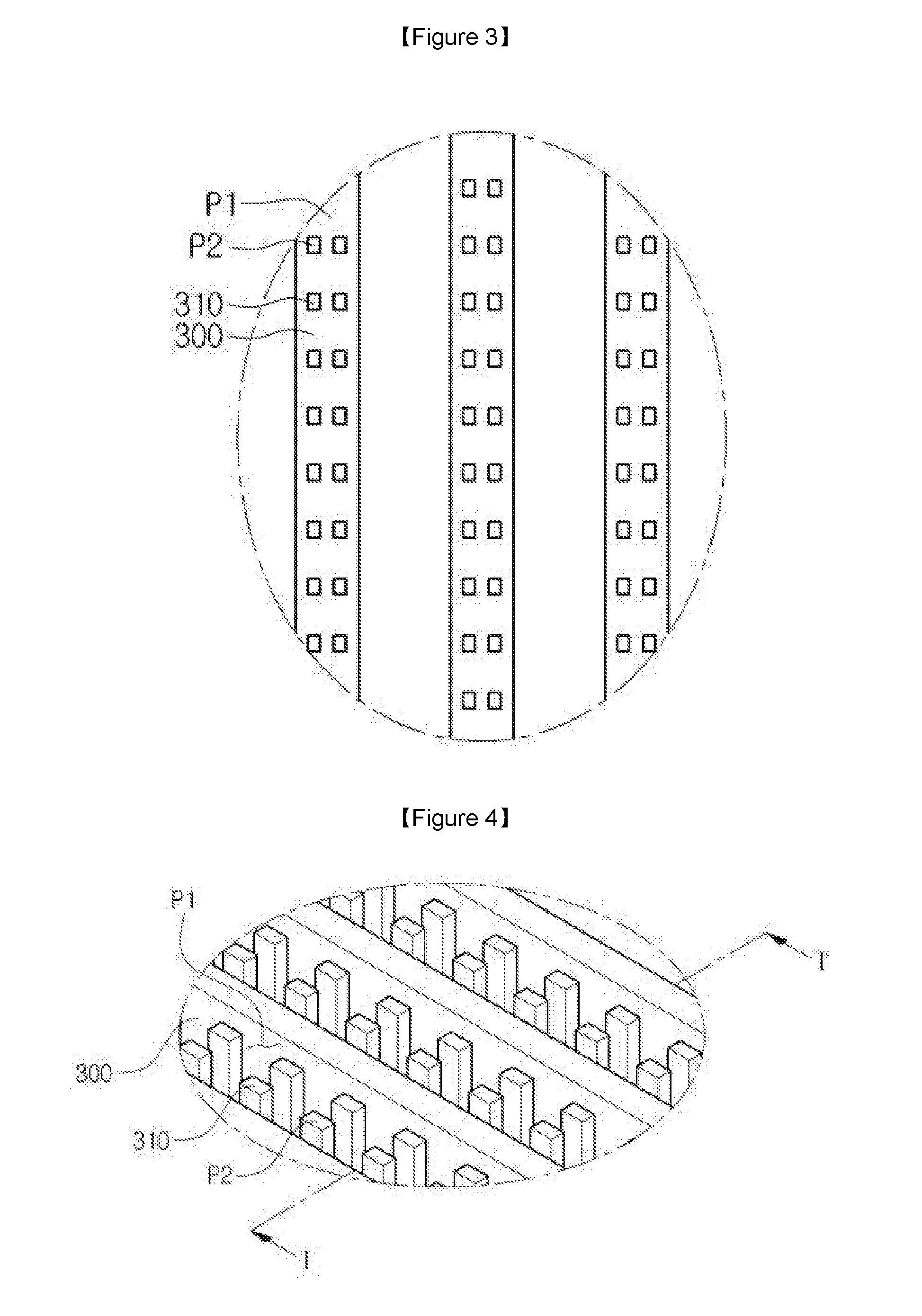
[0037]FIG. 1 is a schematic plan view showing a touch window according to the embodiment. FIG. 2 is a plan v...


PUM


Abstract

Disclosed is a touch window. The touch window includes a substrate, a sensing electrode on the substrate, and a wire to electrically connect the sensing electrode, and a dummy part is provided in the wire. The touch window includes a substrate, a sensing electrode on the substrate, and a wire to electrically connect the sensing electrode. The wire includes a first wire part and a second wire part adjacent to the first wire part, and the first wire part has a directionality different from a directionality of the second wire part.

Description

TECHNICAL FIELD[0001]The disclosure relates to a touch window.BACKGROUND ART[0002]Recently, as various portable electronic devices, such as mobile phones, PDAs, and laptop computers, have been developed, the requirement for compact-size flat panel displays applicable to the portable electronic devices is gradually increased. In this regard, the flat panel displays such as liquid crystal displays (LCDs), plasma display panels (PDPs), field emission displays (FEDs), and vacuum fluorescent displays (VFDs) have been actually studied and commercialized recently.[0003]Metallic wiring patterns provided inside the devices or color filter patterns in the LCD have been realized through various schemes of forming patterns, such as a printing scheme and a photolithography scheme. However, according to the photolithography scheme, processes are complicated in that the photoresist must be laminated, exposed, and developed. Accordingly, the schemes have the limitation in forming fine-patterns.[000...

Claims


Application Information

Patent Timeline
Patent Type & Authority Applications(United States)
IPC IPC(8): G06F3/041
CPCG06F3/0416G06F2203/04112G06F3/04164G06F3/0443
Inventor LEE, SEUNG HEON
Owner LG INNOTEK CO LTD
Why Eureka
Try Eureka