
Voltage-controlled ring oscillator with delay line

a voltage-controlled ring oscillator and delay line technology, which is applied in the direction of pulse generation by logic circuits, pulse techniques, single output arrangements, etc., can solve the problems of poor phase accuracy, high circuitry complexity, and difficult to design a high-frequency multi-phase generator having a reasonable number of phase shift taps

Inactive Publication Date: 2016-06-16
IBM CORP
View PDF3 Cites 2 Cited by
  • Summary
  • Abstract
  • Description
  • Claims
  • Application Information

AI Technical Summary

Benefits of technology

The invention provides a multi-phase oscillator that generates multiple phase-shifted oscillator signals. It includes a ring oscillator with a number of concatenated oscillator delay cells that produce an oscillator signal with a phase shift between them. A phase-blending unit receives two phase-shifted oscillator signals and generates a mid-phase oscillator signal with a phase shift between the phase shifts of the two signals. An interpolator delay line has a number of concatenated interpolator delay cells that generate further phase-shifted oscillator signals based on the mid-phase oscillator signal. This multi-phase oscillator allows for more flexible and precise control of the phase shifts of oscillator signals, which is useful in various applications such as communication systems.

Problems solved by technology

Thus, it is generally difficult to design a high-frequency multi-phase generator having a reasonable number of phase shift taps.
One disadvantage of the disclosed multi-phase voltage-controlled oscillator is that it has a high complexity of the circuitry and a poor phase accuracy since the resistor network introduces a mutual dependency between the individual VCOs.

Method used


Image

  • Voltage-controlled ring oscillator with delay line
  • Voltage-controlled ring oscillator with delay line
  • Voltage-controlled ring oscillator with delay line

Examples


Embodiment Construction

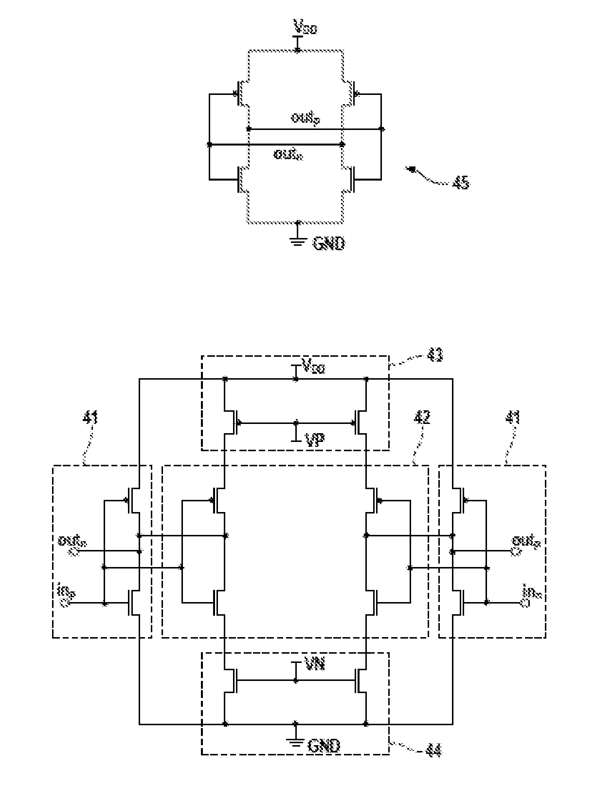
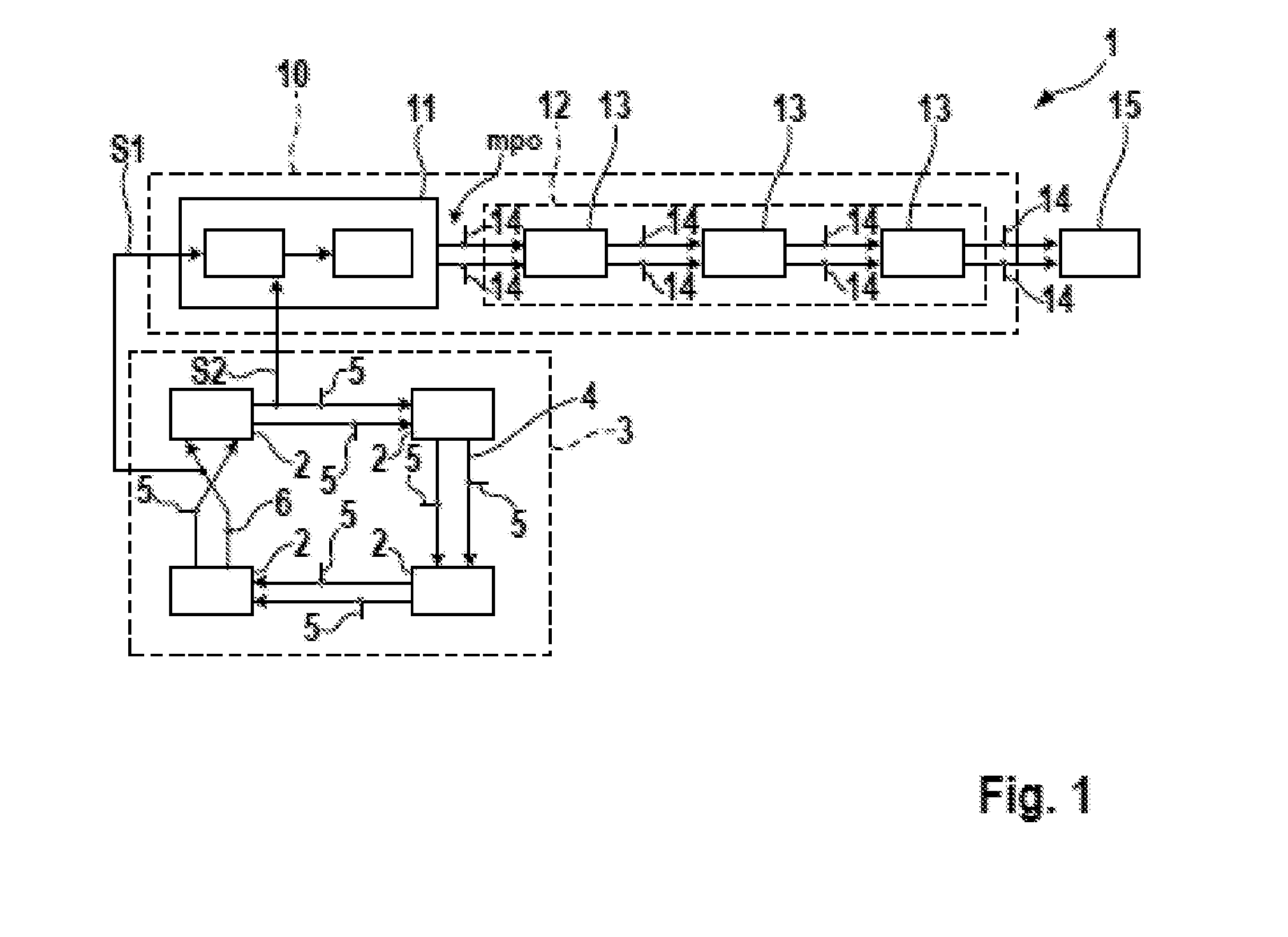
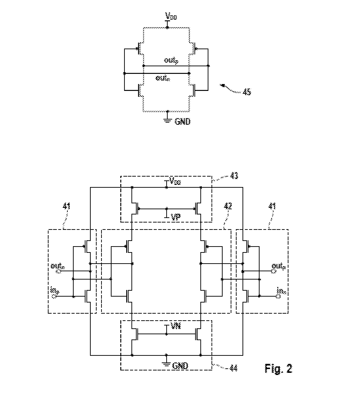
[0015]FIG. 1 schematically shows a configuration of a multi-phase oscillator 1 having a plurality of oscillator delay cells 2 which are serially coupled to form a ring oscillator 3. Each oscillator delay cell 2 can be configured as a differential inverter, a schematic of which is exemplarily shown in FIG. 2. The outputs of the oscillator delay cells 2 are coupled to inputs of a next oscillator delay cell 2, so that a concatenation of oscillator delay cells 2 or a ring oscillator 3 is formed.

[0016]The ring oscillator 3 has a number of oscillator delay cells 2 whose outputs are respectively coupled to an input of a next oscillator delay cell 2. In a differential configuration, each of the oscillator delay cells 2 has a first input, a second input, a first output and a second output. A signal applied to the first input is inverted and the inverted signal is applied to the first output after a predetermined delay. Analogously, a signal applied to the second input is inverted and the inv...


PUM


Abstract

The invention relates to a multi-phase oscillator for generating multiple phase-shifted oscillator signals including: a ring oscillator having a number of concatenated oscillator delay cells which are interconnected to generate an oscillator signal, wherein phase-shifted oscillator signals are generated between the oscillator delay cells; a phase-blending unit configured to receive two phase-shifted oscillator signals and to generate a mid-phase oscillator signal whose phase shift is between the shifts of the two phase-shifted oscillator signals; and an interpolator delay line having a number of concatenated interpolator delay cells to generate further phase-shifted oscillator signals.

Description

CROSS-REFERENCE TO RELATED APPLICATION[0001]This application claims the benefit of priority from United Kingdom Patent Application No. 1422334.1, filed Dec. 16, 2014, the contents of which are incorporated herein by reference.FIELD OF THE INVENTION[0002]The present invention relates to a controlled oscillator formed with a plurality of delay elements and providing multi-phase tabs. In particular, the present invention is related to high-speed controlled oscillators for multiple phases.BACKGROUND[0003]Multi-phase ring oscillators, as e.g. used in multi-phase phase-locked loop circuits, are typically used in receivers of high-speed serial links for the phase adjustment of the sampling clock. They provide multiple phases to a phase interpolator or phase rotator which in turn provides the sampling clock in a clock data recovery circuit. Other fields of application are phased-array antenna systems, where high-frequency multi-phase clock generation is also required.[0004]Multi-phase gener...

Claims


Application Information

Patent Timeline
Patent Type & Authority Applications(United States)
IPC IPC(8): H03K3/03
CPCH03K3/0315H03K2005/00052H03K5/134H03K5/14H03B27/00H03L7/0995H03K3/0322
Inventor KOSSEL, MARCEL A.LIM, DAIHYUNTHIAGARAJAN, PRADEEP
Owner IBM CORP
Learn More