Device for producing an electron beam

a technology of electron beam and electrode, which is applied in the direction of x-ray tube electrode, discharge tube solid thermionic cathode, and associated parts arrangement, etc., and can solve the problem of only achieving the necessary surface field strength

Active Publication Date: 2016-06-23
SIEMENS HEALTHCARE GMBH
View PDF3 Cites 4 Cited by
  • Summary
  • Abstract
  • Description
  • Claims
  • Application Information

AI Technical Summary

Benefits of technology

[0008]Electron beams with a high density are producible thereby in a simple manner. An emission-limiting space charge effect may be reduced because the effective electric field perpendicular to the convex cathode face may be selected to be very high as a disruptive discharge to the concentric extraction electrode is suppressed by the magnetic field present.

Problems solved by technology

In respect of cold cathodes, the necessary surface field strengths may only be achieved with difficulties in this manner.

Method used


Image

  • Device for producing an electron beam
  • Device for producing an electron beam

Examples


Embodiment Construction

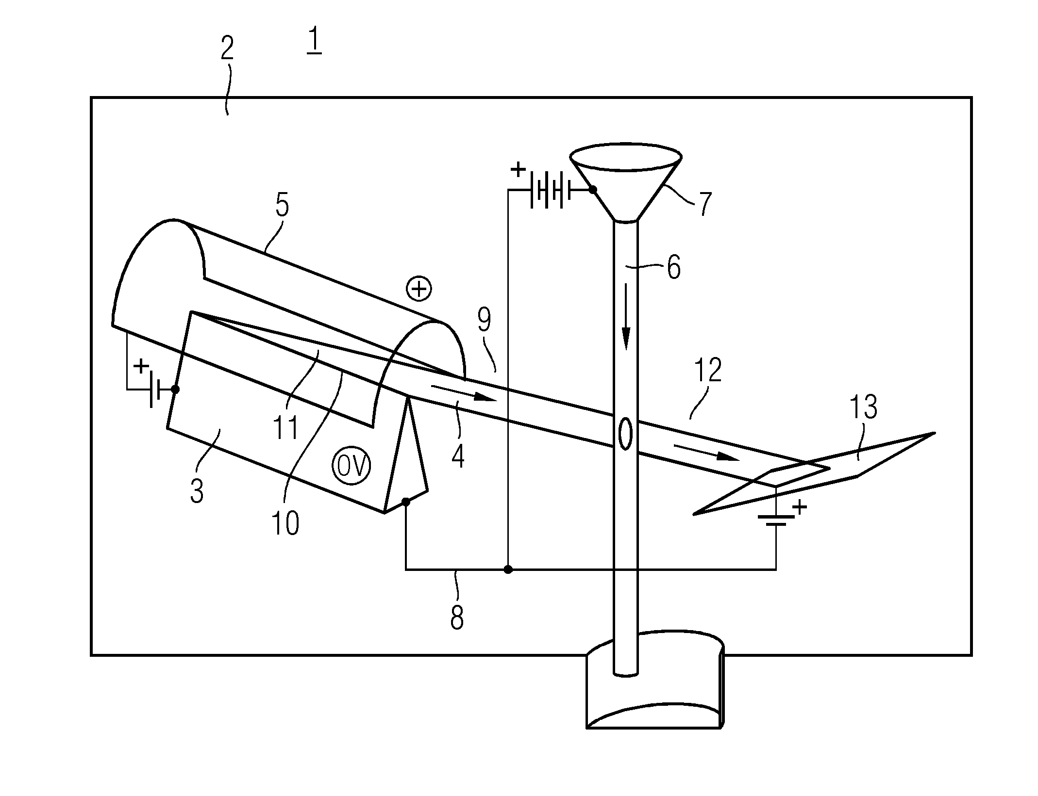
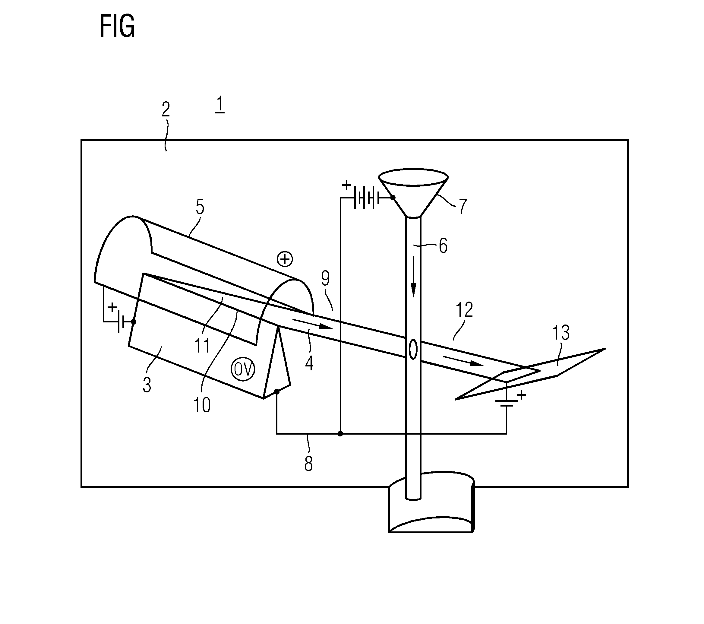
[0013]FIG. 1 depicts a metal jet x-ray tube 1. The metal jet x-ray tube 1 has a vacuum chamber 2 in which a cathode component 3 is arranged. The cathode component 3 serves to extract an electron beam 4. An extraction electrode 5 configured for causing the extraction of the electron beam 4 from the cathode component 3 is provided in the vacuum chamber 2. In the vacuum chamber 2 is located an anode component 7 formed with a liquid metal jet 6. The metal jet 6 is the target for the emitted electron beam 4 of the cathode component 3. An accelerator 8 serves for accelerating the electron beam 4 emitted by the cathode component 3 in the direction and with the target of the anode component 7, at least within a vacuum path 9.

[0014]In an embodiment, the metal jet 6 is realized as a thin metal jet, to the extent that the electrons of the electron beam 4 are, for example, only partly decelerated by the metal jet 6.

[0015]The cathode component 3 has a cathode knife edge 10 such that the cathode ...


PUM


Abstract

A device for the production of an electron beam with high surface strengths. The device has a cathode component with a convex cathode face with a predetermined radius for extracting the electron beam in such an alignment that a magnetic field or the magnetic field lines thereof, for causing the extraction of the electron beam, is almost collinearly to the convex cathode face.

Description

CROSS-REFERENCE TO RELATED APPLICATIONS[0001]This application claims the benefit of DE 10 2014 226 812.5, filed on Dec. 22, 2014, which is hereby incorporated by reference in its entirety.TECHNICAL FIELD[0002]Embodiments relate to a device for producing an electron beam.BACKGROUND[0003]Electron beams with a high beam density are typically obtained from a large-area cathode by way of electrostatic focusing. An example for this is the well-known Pierce gun.SUMMARY AND DESCRIPTION[0004]The scope of the present invention is defined solely by the appended claims and is not affected to any degree by the statements within this summary. The present embodiments may obviate one or more of the drawbacks or limitations in the related art.[0005]In an embodiment, a cathode face is concave and therefore the cathode face has a relatively low electric field strength, i.e. a relatively low maximum current density. In respect of cold cathodes, the necessary surface field strengths may only be achieved...

Claims


Application Information

Patent Timeline
Patent Type & Authority Applications(United States)
IPC IPC(8): H01J29/04H01J35/06H01J29/46
CPCH01J29/04H01J35/06H01J29/46H01J1/16H05G2/005H01J35/066
Inventor HEID, OLIVER
Owner SIEMENS HEALTHCARE GMBH
Why Eureka
Try Eureka