Photovoltaic Power Farm Structure and Installation

a photovoltaic power farm and power installation technology, applied in the direction of heat collector mounting/support, sustainable manufacturing/processing, lighting and heating apparatus, etc., can solve the problems of increasing the cost of individual modules, limiting the practical size of individual modules, and high material and manufacturing costs of crystalline silicon modules, so as to reduce the cost and complexity of photovoltaic power installations.

Inactive Publication Date: 2016-06-23
LUCH DANIEL +1
View PDF10 Cites 2 Cited by
  • Summary
  • Abstract
  • Description
  • Claims
  • Application Information

AI Technical Summary

Benefits of technology

[0090]A further object of the invention is to teach methods to reduce cost and complexity of photovoltaic power installations.

Problems solved by technology

The material and manufacturing costs of the crystalline silicon modules are relatively high.
In addition, the practical size of the individual module is restricted by weight and batch manufacturing techniques employed.
This further increases cost.
However, many thin films require heat treatments which are destructive of even the most temperature resistant polymers.
In addition deposition on glass normally forces expensive and delicate material removal processing such as laser scribing to subdivide the expansive surface into individual interconnected cells remaining on the original glass substrate (often referred to as monolithic integration).
Finally, it is difficult to incorporate collector electrodes over the top light incident surface of cells when employing glass superstrates.
Series interconnecting the large number of resulting individual cells may result in large voltages for a particular module which may be hazardous and require additional expense to insure against electrical shock.
However, because the substrate is conductive, monolithic integration techniques used for nonconductive substrates may involve additional complication.
However handling, repositioning and integration of the multiple individual cells has proven troublesome.
Such an approach reduces the ultimate value of continuous thin film production by introducing a tedious, expensive batch “back end” assembly process.
Many cost and size limitations associated with crystal silicon technology are still present when using “string and tab” interconnections with thin film cells.
In these terrestrial bulk power applications, a significant cost of the installation involves the “balance of system” costs associated with site preparation, construction of installation structures, module placement and power management.
ft.). Cost along with other factors have to date thwarted widespread acceptance of the “shingle” app
In other cases, particularly residential applications, additional complications such as shading and large power variations have led to the introduction of power conditioning devices on individual modules.
Power conditioning of individual module output may significantly increase the “cost per watt” of the collected power.
Packaging of the electronics associated with the power conditioning is responsible for a significant portion of the cost of the conditioning equipment.
Due to the added cost and differing challenges, power modification at the module level has not been widely adopted for more expansive commercial applications such as ground mount or commercial rooftops installations.
However, this approach also has characteristic drawbacks in that deficient performance of one module may adversely affect other modules in an array.
A further issue that has impeded adoption of photovoltaic technology for bulk power collection in the form of solar farms involves installation of multiple modules over expansive regions of surface.
One problem is that the attachment of conductors to the cell strings is often a manual operation requiring tedious operations such as soldering.
Next, unwieldy flexible conductive leads from the module must be directed and secured in position, again a tedious operation.
These are typically tedious manual operations.
Thus, skilled labor having electrical awareness is normally required for bulk installation.

Method used


Image

  • Photovoltaic Power Farm  Structure and Installation
  • Photovoltaic Power Farm  Structure and Installation
  • Photovoltaic Power Farm  Structure and Installation

Examples


example 1

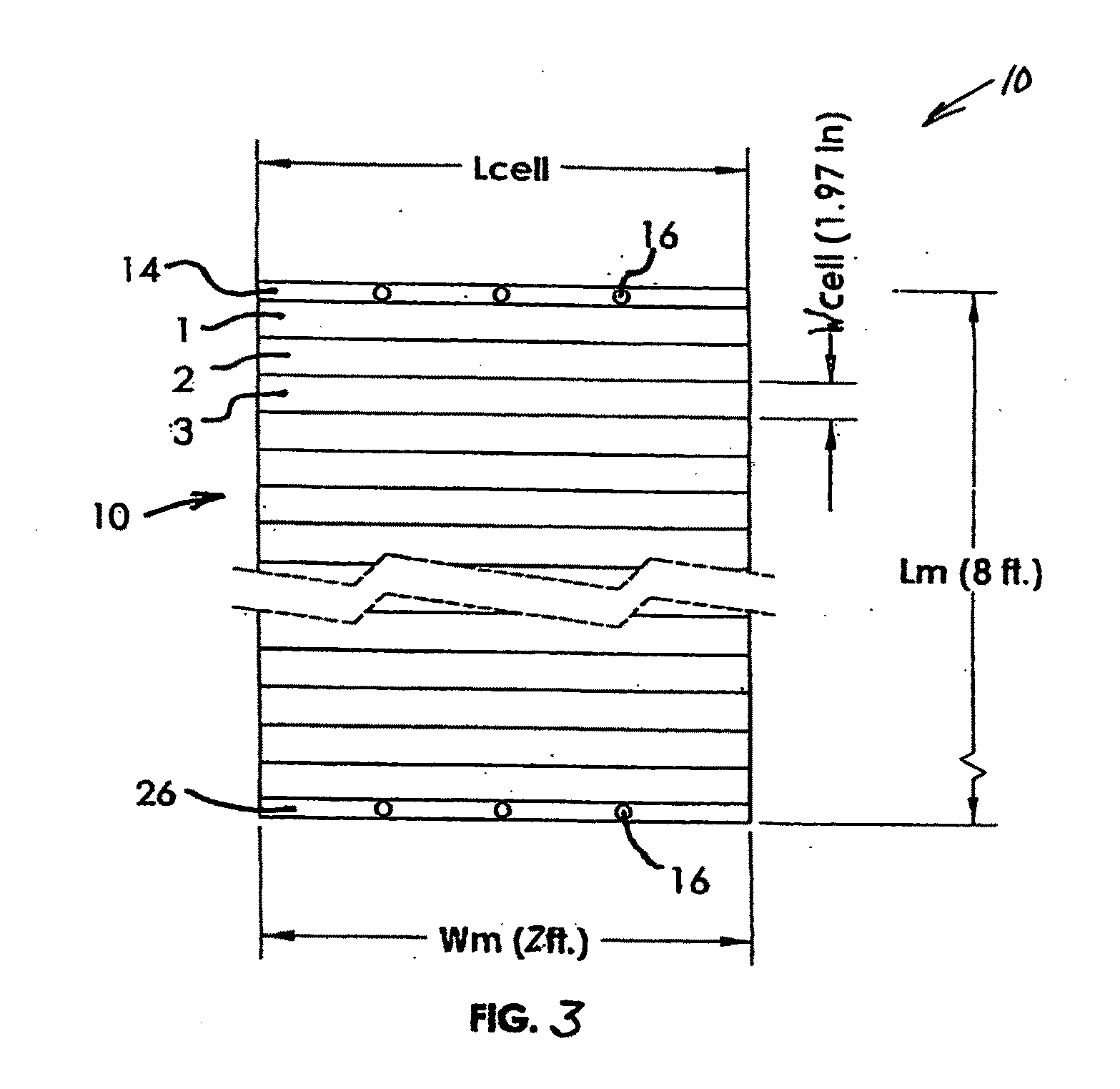
[0299]Modules of multiple interconnected cells comprising thin film CIGS supported by a metal foil are produced. Individual multi-cell modules are constructed according to the teachings of the Luch U.S. patent application Ser. No. 11 / 980,010. As noted, other methods of module construction may be chosen. Each individual cell has linear dimension of width 1.97 inches and length 48 inches (4 ft.). 48 of these cells are combined in series extending approximately 94.5 inches in the module length direction perpendicular to the 48 inch length of the cells. Such a modular assembly of cells is expected to produce typical electrical components on the order of 26 open circuit volts and 18 short circuit amperes. A terminal bar is included to connect to the bottom electrode of the cell at one end of the 8 ft. module length. A second terminal bar is included to connect to the top electrode of the cell at the opposite end of the 8 ft. length. The terminal bars are readily included according to the...

example 2

[0305]In this example, site preparation is generally similar to that of Example 1 and structures are constructed according to the embodiment of FIG. 31. Modules are manufactured and shipped to the installation site in the form of rolls of extended length. For example, a continuous roll of CIGS cells interconnected in series to form a single module is produced. Individual cells have a width dimension of 1.97 inches and length of 48 inches. The module is 100 ft. in length and has terminal bars at each end of the 100 ft. length. There are 608 series connected cells and the terminal bars are about 1 inch wide and extend across substantially the entire 48 inch width of the module. The modules are accumulated in rolls each of which comprises a 100 ft. module as described.

[0306]The rolls are shipped to the installation site. There, workers position one end at the start of an extended channel such as depicted in FIGS. 31 and 32. The module is unrolled using the channel as a guide, optionall...


PUM


Abstract

Unique mounting structures and installation methods for arrays of photovoltaic modules are disclosed. These structures and methods allow for simple, inexpensive and facile production of expansive area solar energy collection facilities. It is emphasized that this abstract is provided to comply with the rules requiring an abstract that will allow a searcher or other reader to quickly ascertain the subject matter of the technical disclosure. It is submitted with the understanding that it will not be used to interpret or limit the scope or meaning of the claims.

Description

CROSS REFERENCE TO RELATED APPLICATION[0001]This application is a Continuation-in-Part of U.S. patent application Ser. No. 12 / 590,222, filed Nov. 3, 2009 entitled Photovoltaic Power Farm Structure and Installation, which is a Continuation-in-Part of U.S. patent application Ser. No. 12 / 156,505, filed Jun. 2, 2008, entitled Photovoltaic Power Farm Structure and Installation, now abandoned. The instant application claims the benefit of priority from all of the above identified applications.BACKGROUND OF THE INVENTION[0002]Photovoltaic cells convert electromagnetic radiation into electrical power. The individual cell produces power which is directed to cell electrodes of opposite polarity. Electrical connections to these electrodes allow harvesting of the photovoltaically generated power.[0003]Photovoltaic power technology relies heavily on material physics and fabrication processes which dictate the characteristics and type of cell. A first cell type is based on the use of single cryst...

Claims


Application Information

Patent Timeline
Patent Type & Authority Applications(United States)
IPC IPC(8): H02S20/30H01L31/05
CPCH01L31/0504H02S20/30F24S20/70F24S25/11F24S25/12F24S25/37F24S25/40F24S25/617F24S25/63F24S25/70F24S30/425F24S2020/12H01L31/02008H02S10/00H02S20/00H02S30/10Y02B10/10Y02E10/47Y02E10/50Y02P80/20
Inventor LUCH, DANIELLUCH, DANIEL RANDOLPH
Owner LUCH DANIEL
Why Eureka
Try Eureka