Ablation probe with deployable electrodes

a technology of electrodes and electrodes, applied in the field of electric field delivery and ablation of target tissue regions, can solve the problems of histological damage to the target tissue, and the difficulty of localizing the heat-induced damage of thermal ablation to the targeted cancerous tissue, so as to achieve selective ablation or destruction of cancerous cells, avoid tissue temperature rise, and reduce the effect of radiation intensity

Inactive Publication Date: 2016-06-30
LAZURE SCI
View PDF5 Cites 2 Cited by
  • Summary
  • Abstract
  • Description
  • Claims
  • Application Information

AI Technical Summary

Benefits of technology

[0008]The present invention provides systems, devices and related methods for applying electric fields for cancerous cell destruction and tissue ablation, e.g., non-thermal tissue ablation. Devices of the present invention will generally be designed to advance an electrode or plurality of electrodes to a target tissue region and apply an electric field to the target tissue region. The electrode or plurality thereof can be positioned such that the applied electric field radiates throughout the target tissue region, including, for example, where the electric field radiates outwardly and in a plurality of directions radially through the target tissue. In certain embodiments, the energy applied to the target tissue region can be selected such that electrically generated heat is minimized and elevations in tissue temperature can be avoided. For example, the applied electric field is can include a lo

Problems solved by technology

In hyper-thermal tumor ablation techniques, high-frequency RF (e.g., “RF thermal ablation”) or microwave sources are used to heat tissue resulting in histological damage to the target tissue.
However, a significant limita

Method used


Image

  • Ablation probe with deployable electrodes
  • Ablation probe with deployable electrodes
  • Ablation probe with deployable electrodes

Examples


Embodiment Construction

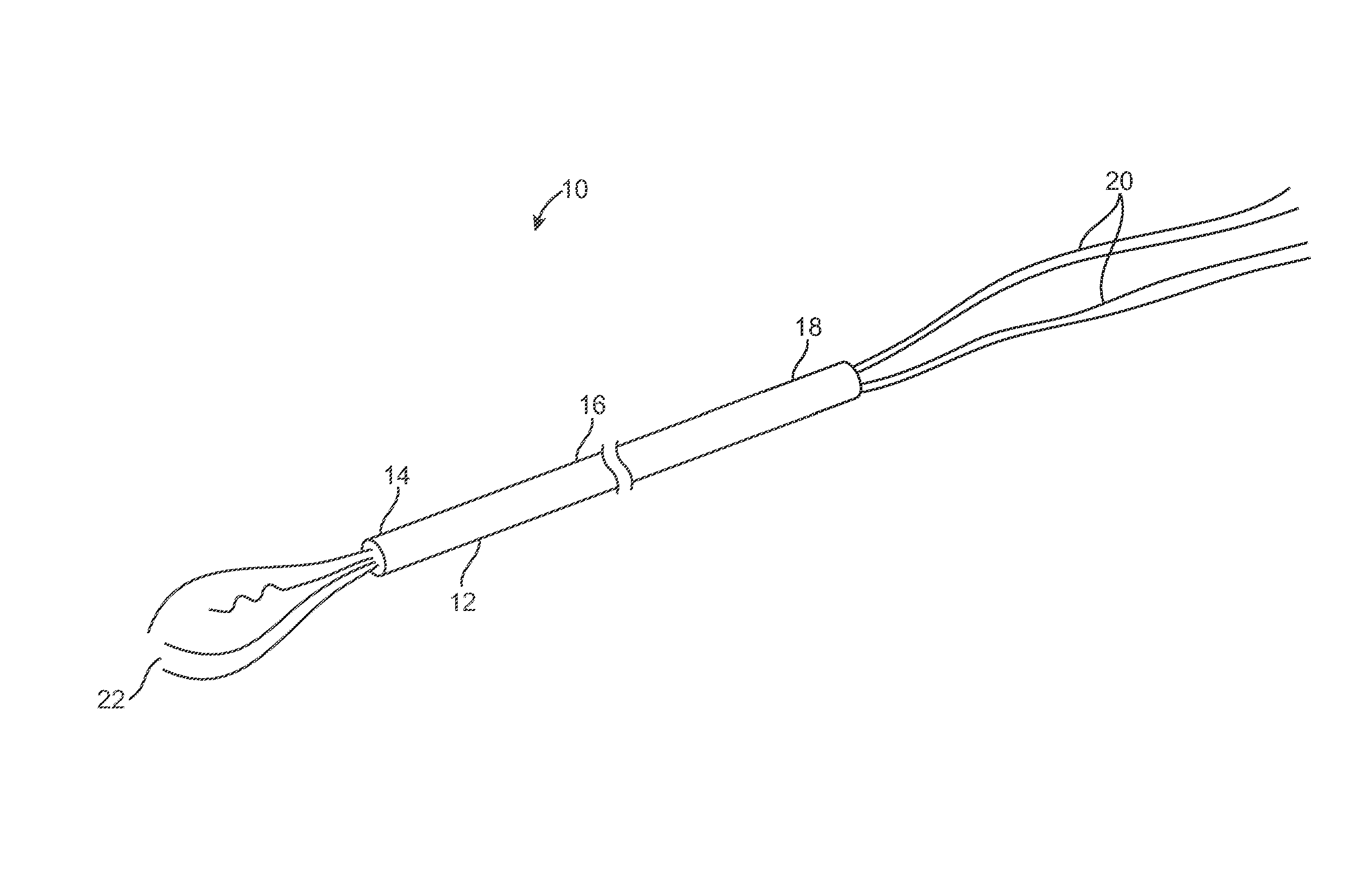
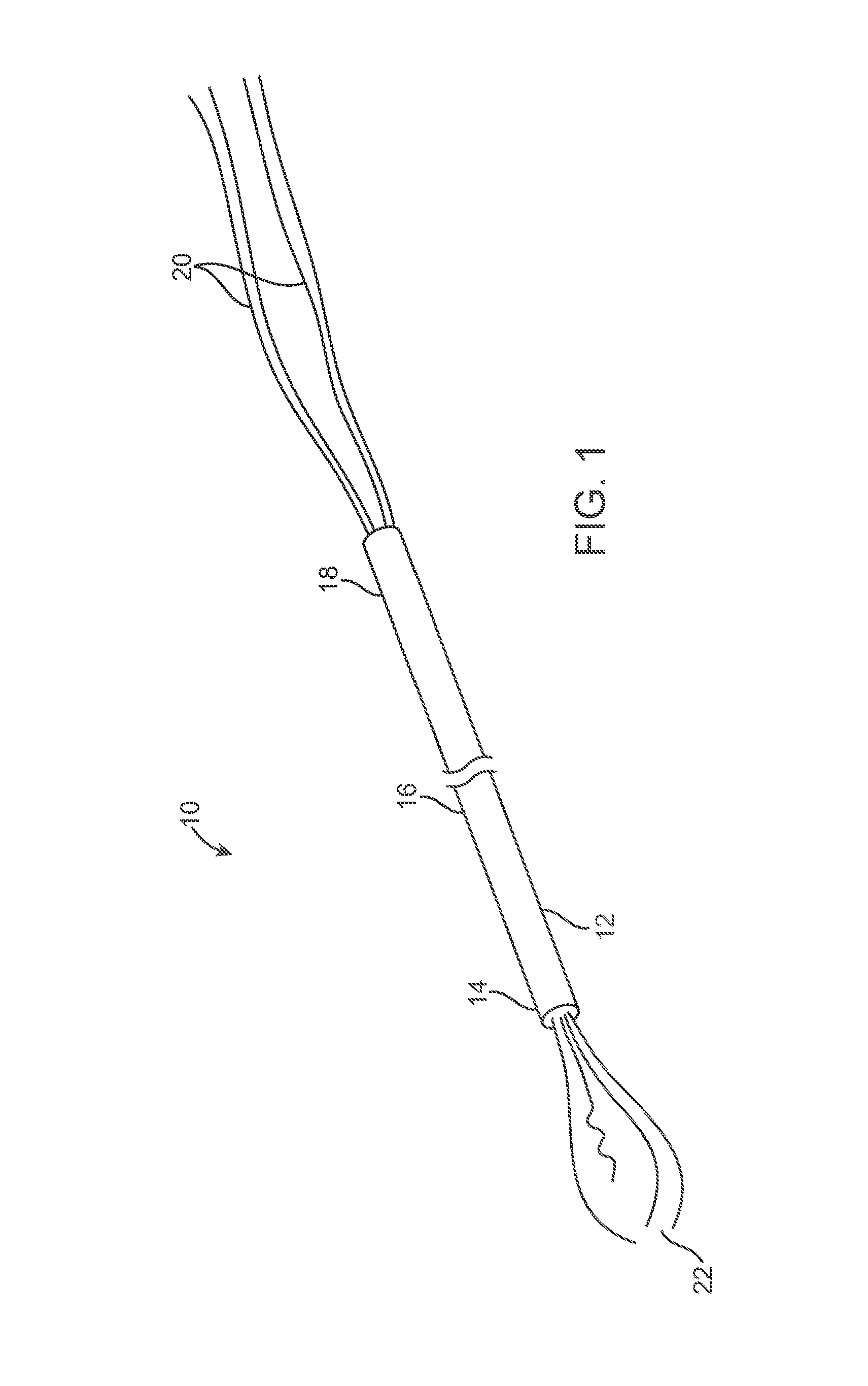
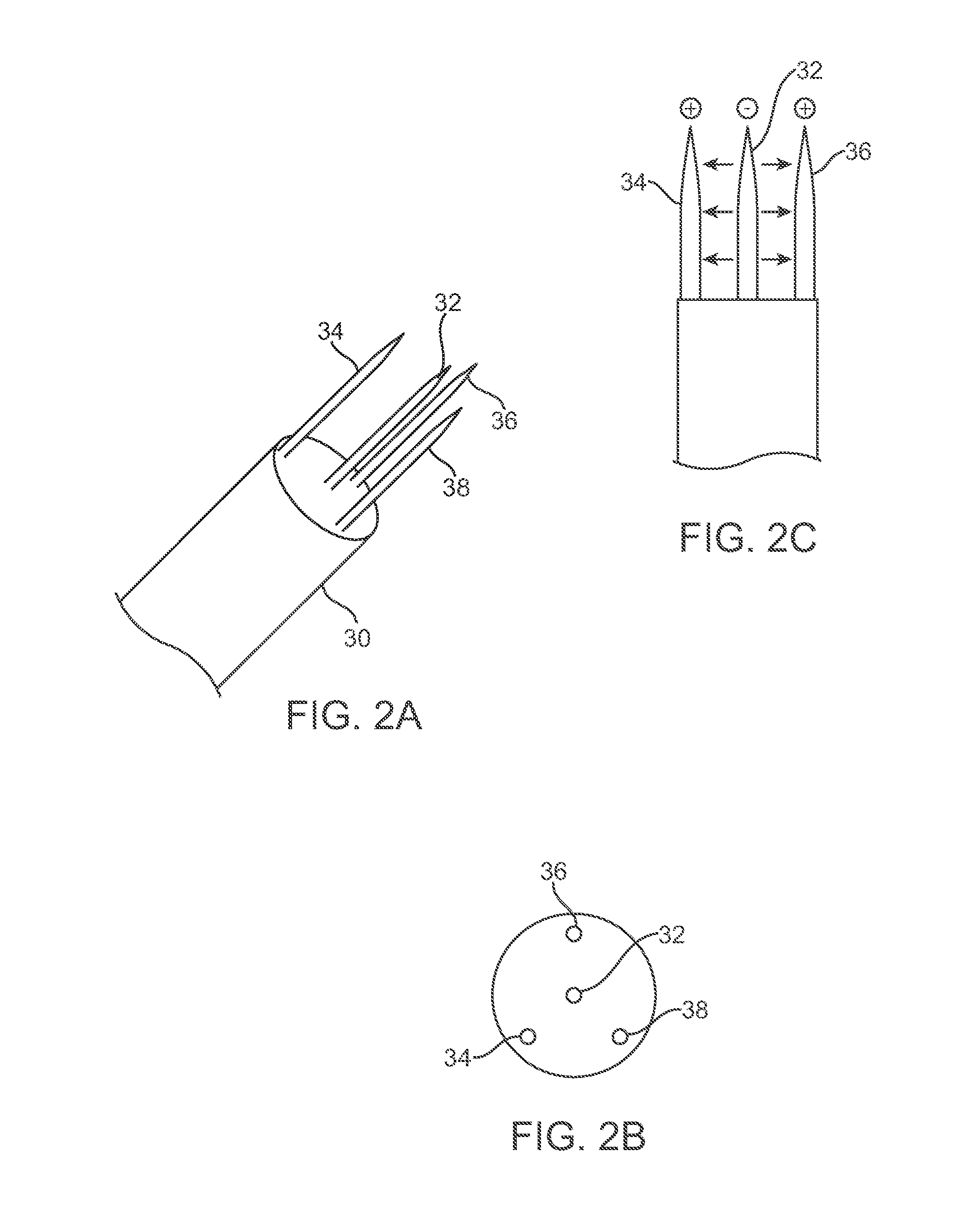
[0034]The present invention provides systems and devices, and related methods for low-power or non-thermal tissue ablation. According to the present invention, an electrode or plurality of electrodes can be introduced into a target tissue region and an electric field applied to the target tissue region. The energy applied to the target tissue region can be selected such that electrically generated heat is minimized and rises in tissue temperature can be avoided, thereby providing low-power or non-thermal ablation of target cells. Devices and methods of the present invention have been demonstrated to be effective in ablating cancerous cells without a thermal effect being a factor in the ablation process, with ablation occurring primarily among abnormally proliferating cells or cells exhibiting unregulated growth (e.g., cancerous cells). Thus, the present invention is advantageous in providing minimally invasive, selective ablation or destruction of cancerous cells, while leaving norm...


PUM


Abstract

The present invention provides systems, devices and related methods for applying electric fields for cancerous cell destruction and tissue ablation. A method can include advancing an ablation probe into a patient; deploying a guide from the delivery member along a guide tissue penetration path, deploying an electrode from the guide along an electrode tissue penetration path, and establishing current flow within the target tissue.

Description

CROSS-REFERENCE TO RELATED APPLICATIONS[0001]The present application is a continuation-in-part of U.S. patent application Ser. No. 13 / 344,373, filed Jan. 5, 2012, which is a continuation of U.S. patent application Ser. No. 11 / 855,940, filed Sep. 14, 2007, now U.S. Pat. No. 8,109,926, issued Feb. 7, 2012, which claims the benefit of U.S. Provisional Patent Application No. 60 / 863,484, filed Oct. 30, 2006, and U.S. Provisional Patent Application No. 60 / 825,660, filed Sep. 14, 2006, the entire contents of which are incorporated herein by reference. The present application is also continuation-in-part of U.S. patent application Ser. No. 14 / 535,166, filed Nov. 6, 2014, which is a divisional of U.S. patent application Ser. No. 12 / 759,611, filed on Apr. 13, 2010, now U.S. Pat. No. 8,915,911, issued Dec. 23, 2014, which is a divisional of U.S. patent application Ser. No. 11 / 855,956, filed Sep. 14, 2007, now U.S. Pat. No. 7,722,606, issued May 25, 2010, which claims the benefit under 35 U.S.C...

Claims


Application Information

Patent Timeline
IPC IPC(8): A61B18/14
CPCA61B18/1477A61B18/1492A61B2018/00791A61B2018/00577A61B2018/00642A61N1/06A61B2018/1407A61B2018/1425A61B2018/143A61B2018/1475A61B2018/00583A61B2018/00714A61B2018/1432A61B2018/1869
Inventor AZURE, LARRY
Owner LAZURE SCI
Why Eureka
Try Eureka