Hydrocarbon production and storage facility

a technology for hydrocarbon production and storage facilities, applied in special purpose vessels, separation processes, borehole/well accessories, etc., can solve the problems of shortening the operational life, increasing fatigue, and destabilising the structure, and achieve the effect of prolonging the unmanned operational period and increasing capacity

Active Publication Date: 2016-06-30
SLLP 134
View PDF7 Cites 6 Cited by
  • Summary
  • Abstract
  • Description
  • Claims
  • Application Information

AI Technical Summary

Benefits of technology

[0025]In use the tank, when not settled upon the gravity base in a shallow water location, is suspended below the production buoy at an intermediate water depth conducive to a temperature stabilisation process for the produced oil collected in th...

Problems solved by technology

Unchecked scour can destabilise the structure...

Method used


Image

  • Hydrocarbon production and storage facility
  • Hydrocarbon production and storage facility
  • Hydrocarbon production and storage facility

Examples


Embodiment Construction

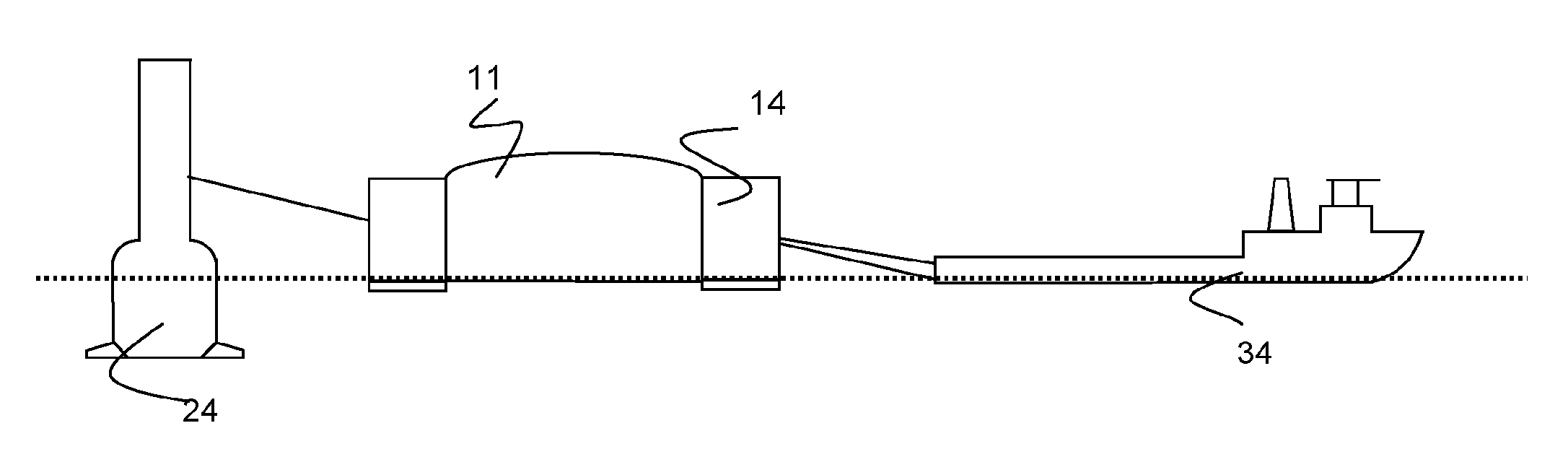
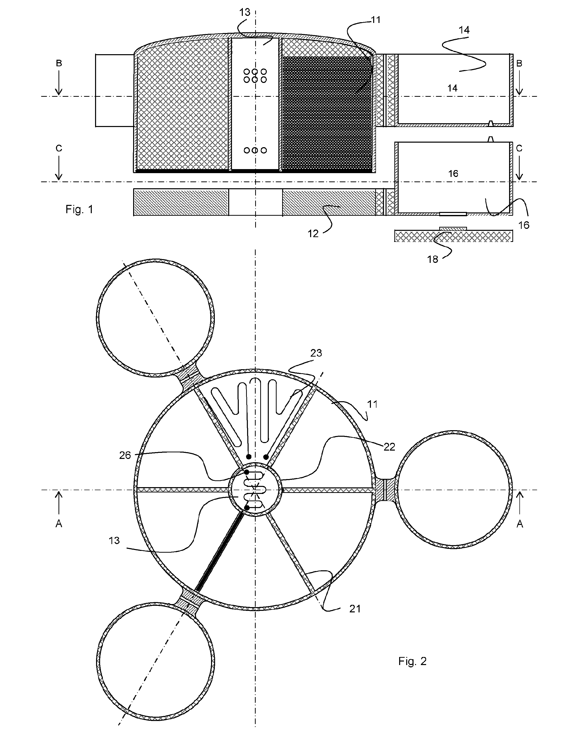
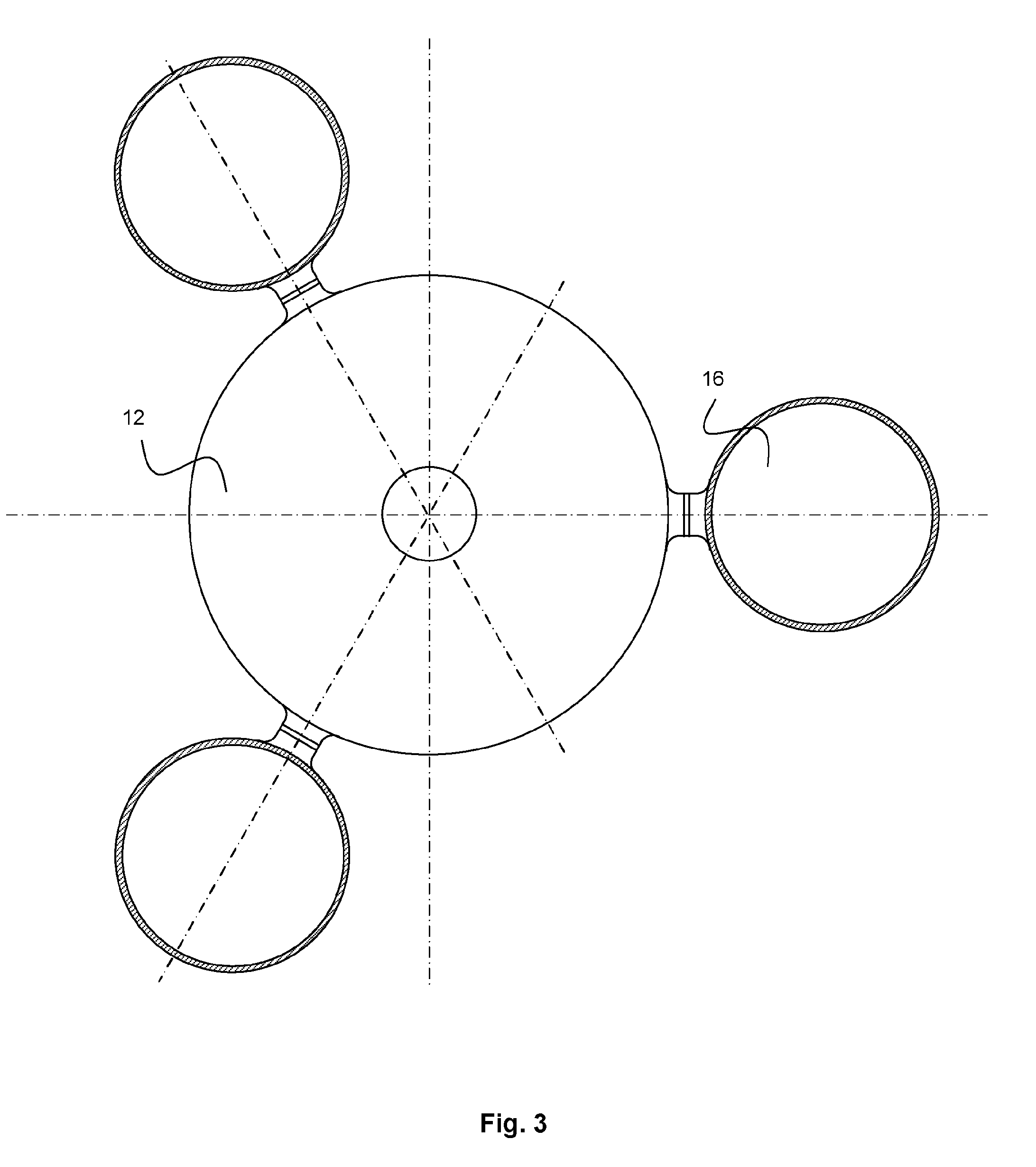
[0082]Referring to FIG. 1, a deployable and recoverable storage facility comprises a storage tank 11 associated with a separable gravity base 12, and ballast tanks 14, 16, respectively for each of the storage tank 11 and the gravity base 12. Multiple ballast tanks 14, 16, (only one shown) are provided around the storage facility. Releasable feet 18 which may be configured for height adjustment to compensate for variable seabed conditions are attached to each of the base ballast tanks.

[0083]The storage tank 11 includes a central separator zone 13 configured to receive produced oil for stabilisation by separation of water and volatiles under a temperature controlled stabilisation process.

[0084]Referring to FIG. 2, the storage tank 11 is compartmentalised by radially extending internal walls 21 around the central column separator zone 13 which is defined by an upright tubular column 22. Each sector shaped compartment may include a heater element 23 for maintaining a desired temperature...


PUM

PropertyMeasurementUnit
Temperatureaaaaaaaaaa
Poweraaaaaaaaaa

Abstract

A subsea fluids storage facility comprises a tank (11) for holding and separating fluids which is equipped with ballast capacity (14) and a separable base (12) to be deployed upon the seabed in shallow or deep water, and the storage facility is connectable to a surface production facility, especially a buoy (24) for processing fluids. In deep water the tank (11) is held at a depth above the base (12) for temperature controlled stabilisation of produced oil in the tank (11).

Description

FIELD OF THE INVENTION[0001]This invention relates to the field of offshore petroleum production, and provides a submersible hydrocarbon fluid storage and water separation facility useful in the recovery of oil and gas from a subsea well. A process for recovery of hydrocarbon fluids is also provided.BACKGROUND TO THE INVENTION[0002]Considerable efforts have been made in the petroleum industry to exploit offshore resources i.e. hydrocarbon oil and gas-bearing reservoirs which are accessible from a marine vessel or offshore installation via a riser connected to a subsea wellhead. Whereas many reservoirs have been accessible by coastal inshore or shallow water facilities, increasingly prospecting for such reservoirs is conducted in challenging deep marine environments. The facilities required for production and export of the hydrocarbons has become correspondingly complex and expensive. The literature on vessels and structures designed for this purpose is extensive.[0003]Whereas the oi...

Claims


Application Information

Patent Timeline
IPC IPC(8): E02B17/02B01D19/00C10G31/06B63B35/44C10G33/06C10G31/09B01D17/02E21B43/36
CPCE02B17/02B01D17/0208B01D19/0036E21B43/36B63B2035/4486C10G33/06C10G31/09C10G31/06B63B35/44B63B22/06B63B22/28C09K2208/22C10G2300/1033C10G2300/4062
Inventor SELWA, RICHARD
Owner SLLP 134
Why Eureka
Try Eureka