
Method of manufacturing optical waveguide device and laser processing apparatus

a laser processing and optical waveguide technology, applied in the direction of manufacturing tools, instruments, other domestic objects, etc., can solve the problems of reducing production efficiency and increasing costs, and achieve the effects of suppressing equipment investment, saving costs, and simple structur

Active Publication Date: 2016-06-30
SHINKO ELECTRIC IND CO LTD
View PDF2 Cites 9 Cited by
  • Summary
  • Abstract
  • Description
  • Claims
  • Application Information

AI Technical Summary

Benefits of technology

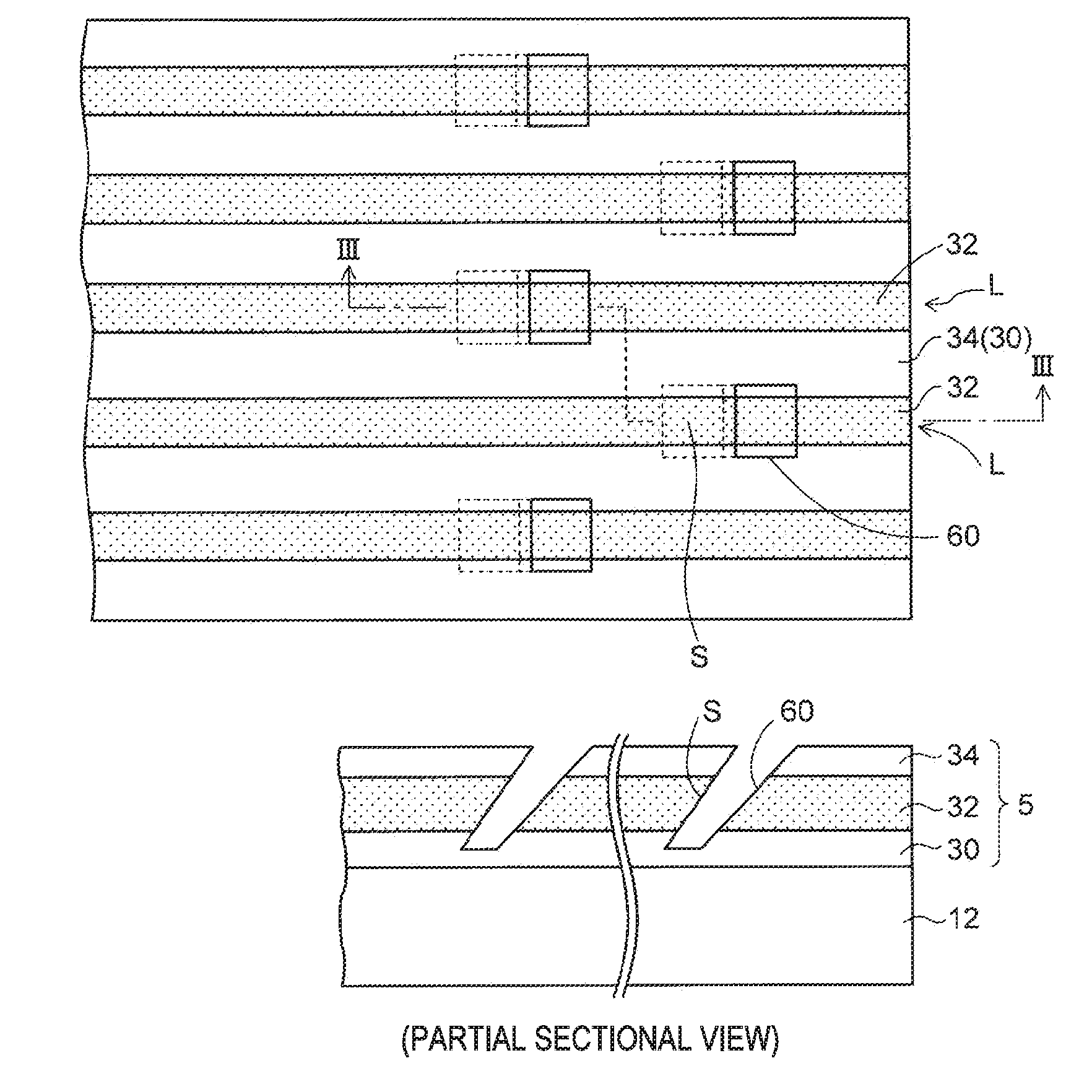
This patent describes a method for making optical waveguide devices by using an inclined surface to change the optical path of light. The method is cost-effective and efficient, as there is no need to set the laser in a special way or arrange the optical waveguide in a specific way. By using a simple reflection mechanism, the optical path conversion inclined surface can be formed in each optical path of the waveguide. Additionally, the laser can be irradiated through a mask with multiple openings, allowing for simultaneous formation of optical path conversion inclined surfaces in multiple optical paths.

Problems solved by technology

For this reason, a laser processing apparatus of a special specification is required, which increases the cost.
Also, since the one recess portion having the inclined surface is sequentially formed by one laser irradiation, the processing time is considerably prolonged in order to form the inclined surfaces in a plurality of core layers of the optical waveguide, which lowers the production efficiency.

Method used


Image

  • Method of manufacturing optical waveguide device and laser processing apparatus
  • Method of manufacturing optical waveguide device and laser processing apparatus
  • Method of manufacturing optical waveguide device and laser processing apparatus

Examples


Embodiment Construction

[0037]Hereinafter, an exemplary embodiment will be described with reference to the accompanying drawings.

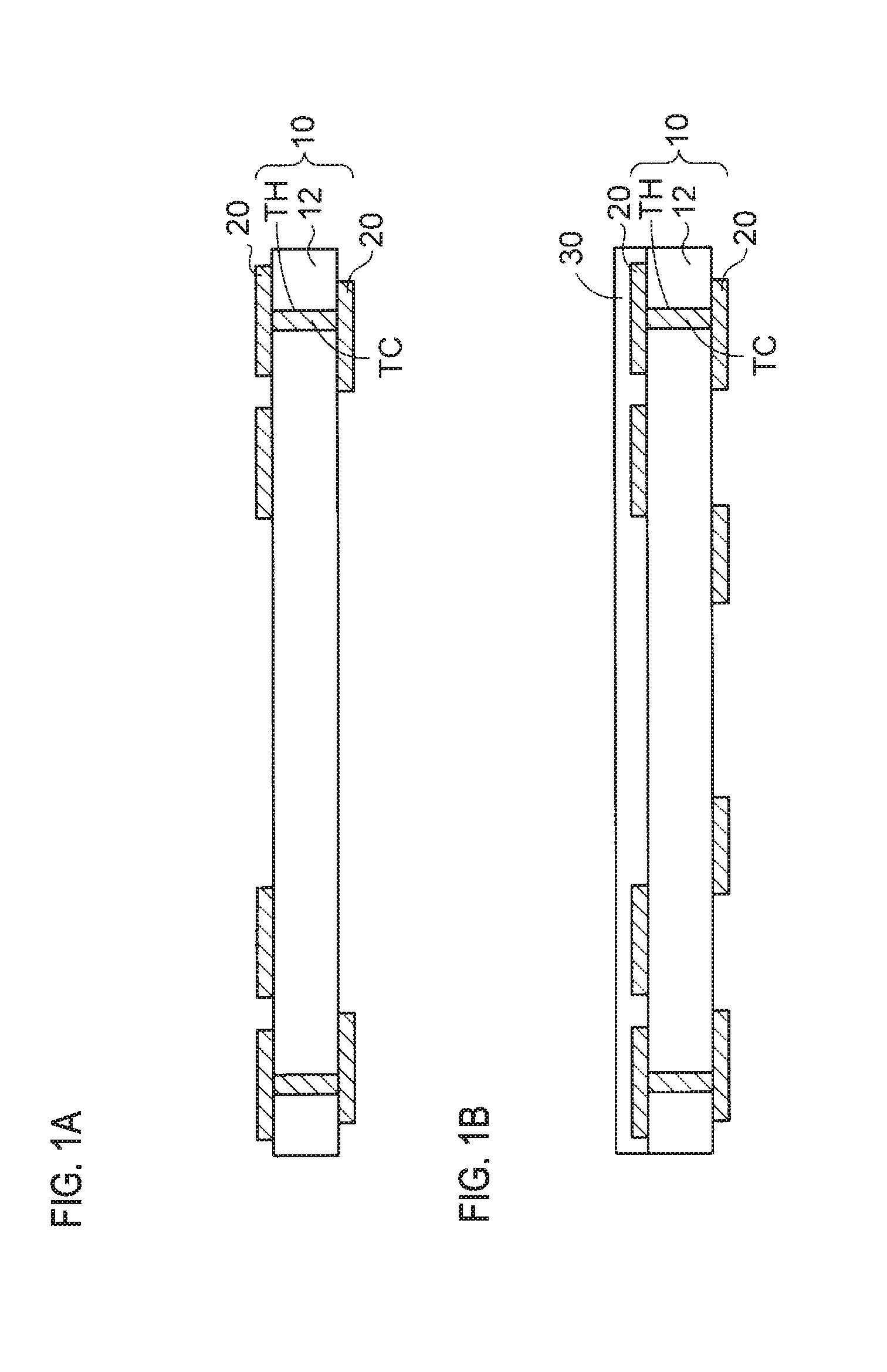
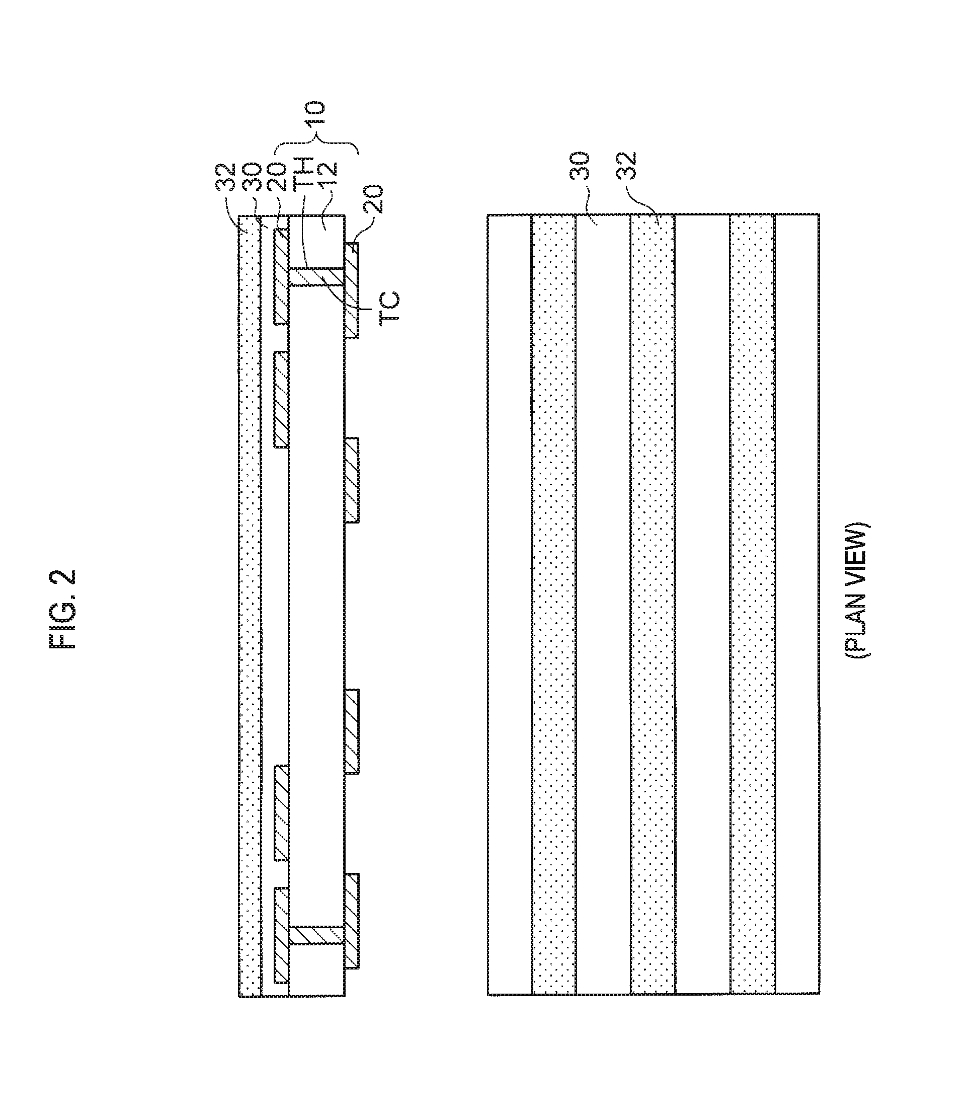
[0038]FIGS. 1A to 10 show a method of manufacturing an optical waveguide device of an exemplary embodiment, and FIGS. 11 and 12 show an optical waveguide device of the exemplary embodiment.

[0039]According to a method of manufacturing an optical waveguide device of an exemplary embodiment, a wiring board 10 configured to handle an electric signal is first prepared, as shown in FIG. 1A. In the wiring board 10, both surfaces of an insulating substrate 12 are formed with wiring layers 20, respectively. The insulating substrate 12 is formed with through-holes TH penetrating the insulating substrate in a thickness direction, and the through-holes TH are filled with through-conductors IC. The wiring layers 20 on both surfaces are connected each other via the through-conductors TC.

[0040]On a lower surface of the insulating substrate 12, a solder resist layer (not shown) having an opening...


PUM

PropertyMeasurementUnit
Timeaaaaaaaaaa
Optical propertiesaaaaaaaaaa
Reflectionaaaaaaaaaa

Abstract

An optical waveguide having a plurality of optical paths is formed on a substrate. A reflection mechanism is arranged above the optical waveguide. The reflection mechanism includes mirror components, each of which has an inclined reflective surface, and a mask having a plurality of openings. Laser is irradiated to the mirror components and optical path conversion inclined surfaces are formed in the plurality of optical paths at the same time by the laser reflected on the mirror components.

Description

CROSS-REFERENCE TO RELATED APPLICATION[0001]The present application claims priority from Japanese Patent Application No. 2014-264324 filed on Dec. 26, 2014, the entire content of which is incorporated herein by reference.BACKGROUND[0002]1. Technical Field[0003]The present disclosure relates to a method of manufacturing an optical waveguide device and a laser processing apparatus.[0004]2. Related Art[0005]An optical waveguide device has been known in which an optical waveguide for guiding an optical signal is formed on a wiring board that handles an electric signal. The optical waveguide device is an optoelectronic composite board, and can transmit a high-speed signal in form of the optical signal so as to make up for a limit of a transmission speed of the electric signal.[0006]An optical path conversion mirror is arranged at an end of the optical waveguide, and an optical element is mounted on the wiring board so that it is optically coupled with the optical path conversion mirror o...

Claims


Application Information

Patent Timeline
IPC IPC(8): G02B6/138G02B6/122
CPCG02B6/138G02B6/122G02B2006/12147G02B2006/12069G02B2006/12173G02B6/428G02B6/4214G02B6/43G02B6/1221G02B2006/1219B29D11/00663
Inventor YANAGISAWA, KENJI
Owner SHINKO ELECTRIC IND CO LTD
Learn More