

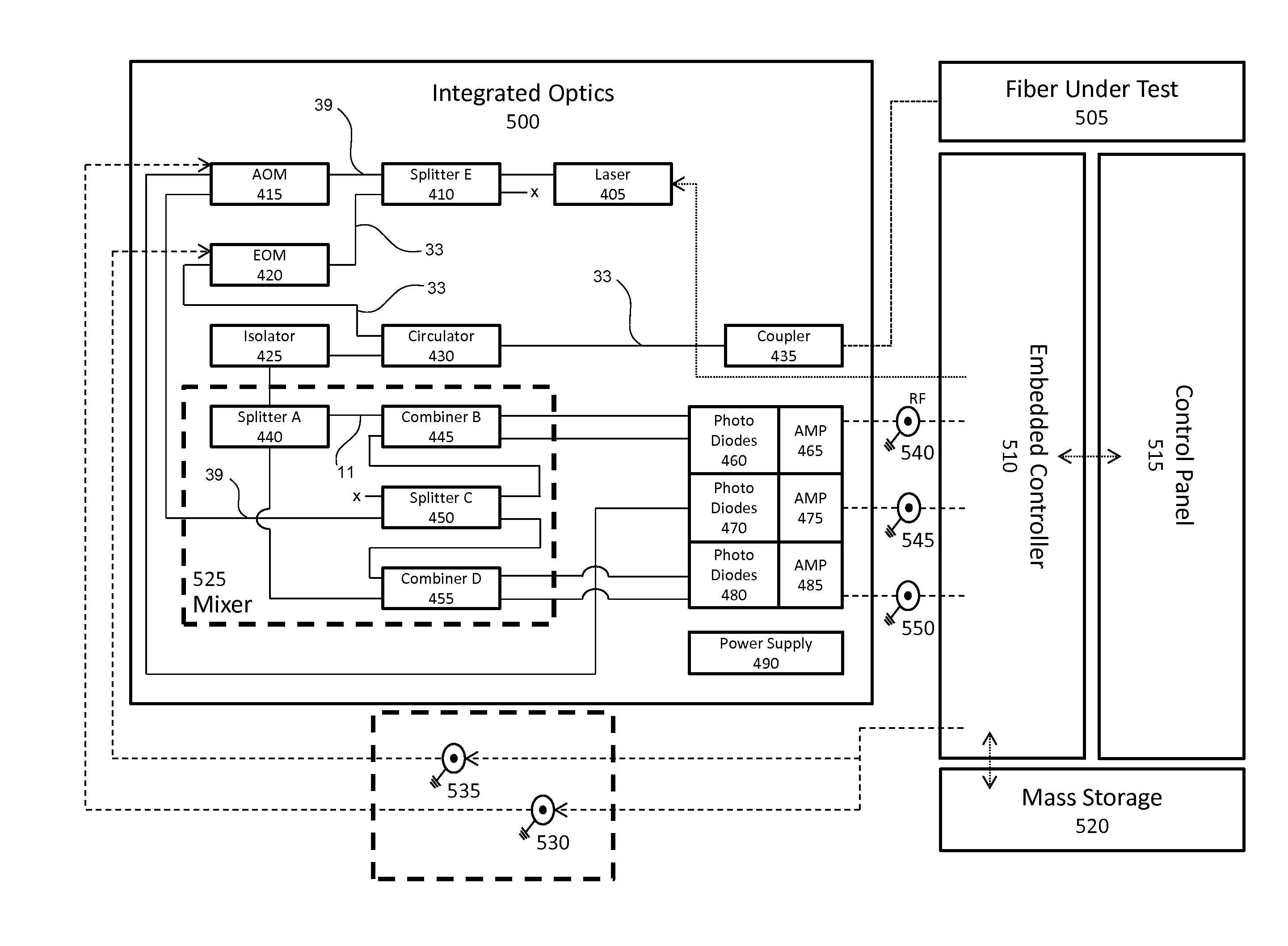
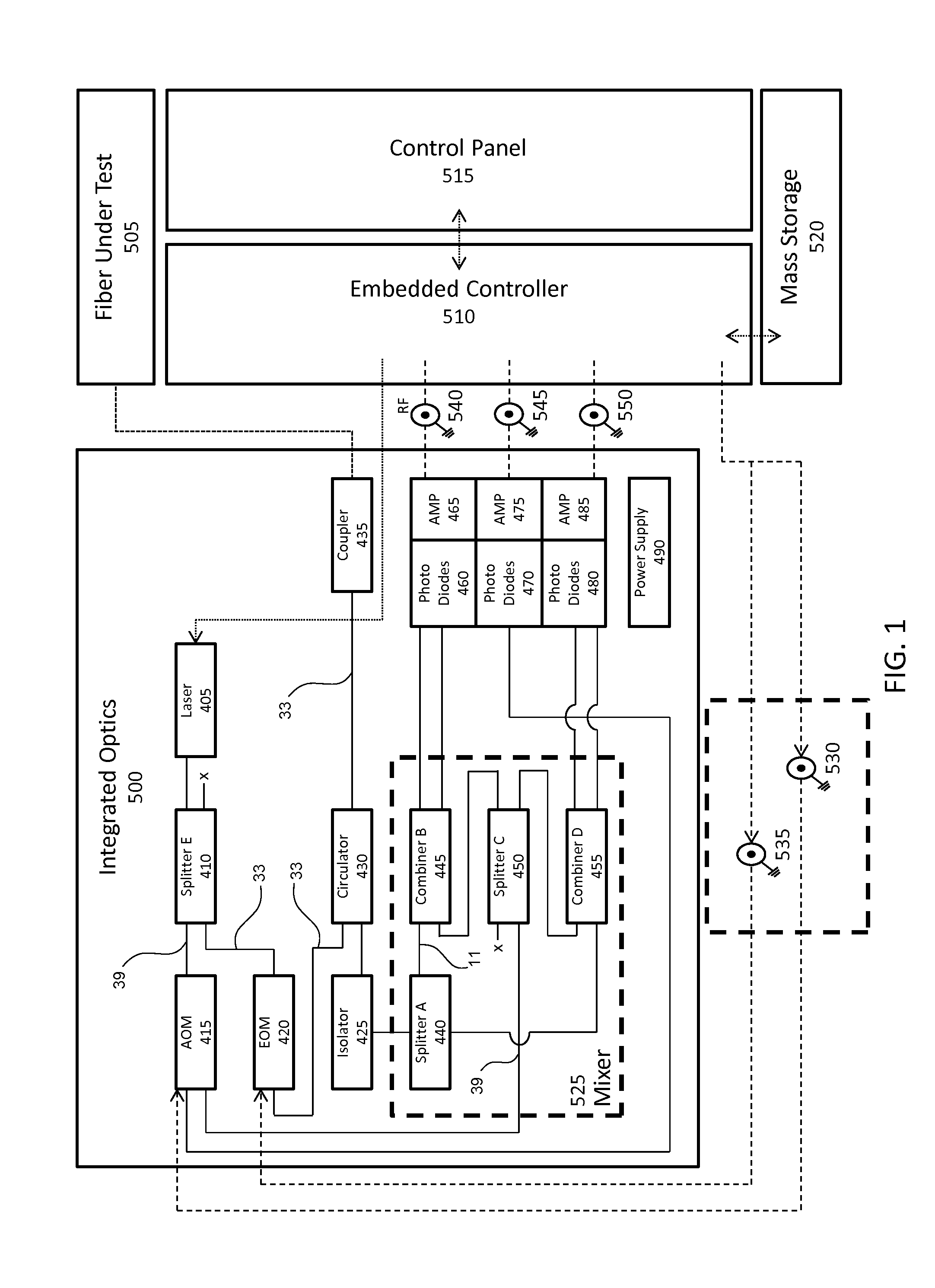
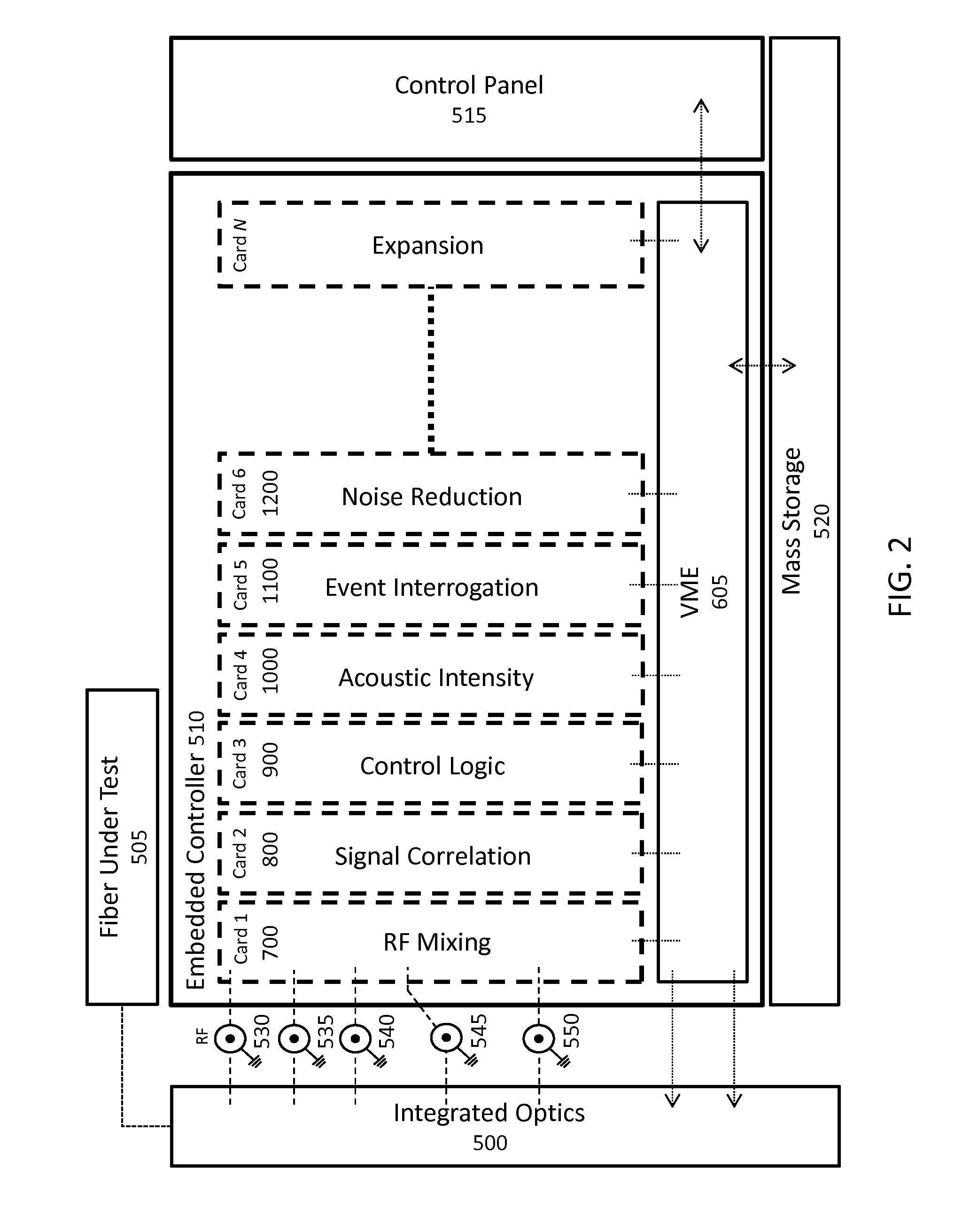
Real-time fiber optic interferometry controller
a fiber optic interferometry controller and real-time technology, applied in the field of fiber optic sensing, can solve the problems of difficult reduction of acoustic signals impinging on system hardware that contribute to what is termed signal noise floor, and the difficulty of managing fiber noise, so as to improve the utility and/or utility of the sensing system, reduce the impact of acoustic noise and noise floor, and reduce the effect of noise floor
- Summary
- Abstract
- Description
- Claims
- Application Information
AI Technical Summary
Benefits of technology
Problems solved by technology
Method used
Image

Examples
Embodiment Construction
[0037]In the following description, and for the purposes of explanation, numerous specific details, process durations, and / or specific formula values are set forth in order to provide a thorough understanding of the various aspects of exemplary examples. It will be understood, however, by those skilled in the relevant arts, that the apparatus, systems, and methods herein may be practiced without these specific details, process durations, and / or specific formula values. It is to be understood that other examples may be utilized and structural and functional changes may be made without departing from the scope of the apparatus, systems, and methods herein. In other instances, known structures and devices are shown or discussed more generally in order to avoid obscuring the exemplary examples. In many cases, a description of the operation is sufficient to enable one to implement the various forms, particularly when the operation is to be implemented in software. It should be noted that...
PUM
 Abstract
Description
Claims
Application Information