Unlock instant, AI-driven research and patent intelligence for your innovation.

Recuperated Gas Turbine Engine

Active Publication Date: 2016-07-07
UNITED STATES OF AMERICA
View PDF2 Cites 15 Cited by
  • Summary
  • Abstract
  • Description
  • Claims
  • Application Information

AI Technical Summary

Benefits of technology

The invention describes an engine with a compressor, turbine, heat exchanger, and combustor. The heat exchanger is designed to preheat the air leaving the compressor by transferring heat from the turbine exhaust. The combustor can then mix fuel with the preheated air and ignite it. This design allows for more efficient heat transfer and better fuel mixing, resulting in improved engine performance. Additionally, the patent describes the use of two heat exchangers, one for preheating the air and another for transferring additional heat to the preheated air. This further improves engine performance.

Problems solved by technology

However, they have difficulty competing with piston engines due to inferior fuel efficiencies.
This may be due to scaling effects.
For example, gas flows at small length scales are characterized by low Reynolds numbers, which means that inertial effects become less important than viscous effects, viscous friction wastes more power, and turbomachinery becomes less efficient.
Small turbomachinery tip clearances and trailing edge thicknesses tend to be relatively larger, relative to blade chord and span, than in large engines, and this also leads to larger losses and lower compression and expansion efficiencies.
Unwanted heat transfers, particularly heat losses from the burner and heat transfer to the compressor, can reduce fuel efficiency severely in small turbines.
However, when these components were assembled into a complete engine, it only reached 6% efficiency.
Annular combustors are common in gas turbines but they are somewhat complex, requiring multiple fuel injectors to be spaced evenly around the ring, to spread out the heat of combustion evenly.
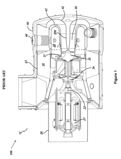
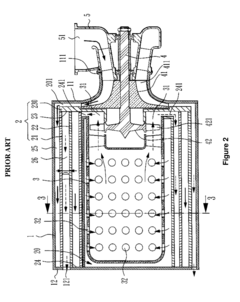
Although advantageous in many respects, the FIG. 2 layout does suffer from certain drawbacks.
One problem is the axial thrust on the bearings.
Compressor and turbine rotors generate thrust due to imbalanced gas pressures.
This means that their values add together rather than balancing each other out, leading to potentially very high net axial loads on the bearings.
Since the life of a rolling element bearing is proportional to the load cubed, this can lead to short bearing life and premature bearing failure.
Along with high bearing thrust loads, another disadvantage of the FIG. 2 prior art layout is gas leakage.
However, this shaft will be hot.
It would be difficult to position a contact seal in that location because the contact seal would overheat.
A non-contact labyrinth seal might make sense but due to the high gas pressure difference, the leakage rate would be quite substantial through this area, and this would substantially reduce the overall engine efficiency.
In this engine layout there is no readily apparent way to minimize the gas leakage rate along the rotating shaft.
Another disadvantage of the engine layouts in both prior art FIG. 1 and FIG. 2 relates to heat transfer to the compressor diffuser.
Either way makes the compressor consume more shaft power and makes the engine, as a whole, less efficient.
In other words, heat transfer to the compressor diffuser is bad because it requires more shaft power to compress the gas enough to reach the target outlet pressure.
Another way of looking at this is to say that heat transfer to any part of the compressor will reduce its efficiency, relative to an adiabatic (i.e., unheated) compressor.
Another problem in many prior art microturbines is the difficulty of keeping the bearings cool, especially the one closest to the turbine rotor.
If the rotor assembly is made longer to make room, shaft dynamics problems can result.
However, air bearings have some disadvantages as well, including air foil touchdown during start / stop operation, the need to be kept very clean due to tight clearances, complex rotordynamics, relatively high cost, and the need for considerable testing and development work to ensure high reliability.

Method used


Image

  • Recuperated Gas Turbine Engine
  • Recuperated Gas Turbine Engine
  • Recuperated Gas Turbine Engine

Examples


Embodiment Construction

[0031]One or more embodiments or implementations are hereinafter described in conjunction with the drawings, where like reference numerals refer to like elements throughout, and where the various features are not necessarily drawn to scale.

[0032]In general, FIGS. 3, 4, and 5 show exemplary embodiments of the invention. Specifically, FIG. 3 is a recuperated gas turbine engine 300, in accordance with an exemplary embodiment of the invention. FIG. 4 is a view of a recuperated gas turbine engine as seen from the exhaust outlet end 400, in accordance with an exemplary embodiment of the invention. FIG. 5 is a cross-section view of a recuperated gas turbine engine 500, in accordance with an exemplary embodiment of the invention.

[0033]FIG. 6 is an alternative cross-section view of a recuperated gas turbine engine 600, in accordance with an exemplary embodiment of the invention. One of ordinary skill in the art will note that the size of the engine can be varied to exemplify different embodi...


PUM


Abstract

A gas turbine engine that includes a compressor, a turbine, a heat exchanger, and a combustor. The compressor is mounted on a rotating shaft with at least one rotor with an inlet and an outlet, and at least one diffuser downstream from each rotor. The turbine includes at least one stator, and at least one rotor with an inlet and outlet located downstream of each stator, and mounted on the rotating shaft as the at least one of the compressor rotors. The inlet of the compressor rotor faces toward the outlet of the turbine rotor. The heat exchanger is configured to preheat the compressed air leaving the compressor by transferring heat from the turbine exhaust. The combustor can be configured for mixing fuel with the compressed air, either upstream or downstream from the heat exchanger, and further configured for igniting the preheated fuel / air mixture located downstream from the heat exchanger.

Description

CROSS-REFERENCE TO RELATED APPLICATIONS[0001]This application claims priority to provisional patent application entitled, “Recuperated Gas Turbine Engine,” filed on Sep. 9, 2014, and assigned U.S. Application No. 62 / 047,855; the entire contents of which are hereby incorporated by reference.FIELD OF THE INVENTION[0002]The present disclosure relates generally to gas turbine engines.BACKGROUND[0003]Historically, gas turbine engines have been able to achieve much better life and reliability than internal combustion (IC) engines, perhaps because they employ a steady flow combustion process, fewer moving parts, no reciprocating motion, and no surfaces in rubbing contact. Gas turbines are typically also adaptable to using a wider range of fuels. They generate almost no vibration and steady output torque, while IC engines more commonly generate peak:mean torque levels between 4:1 and 16:1. Turbines also produce only high-frequency noise, which is easier to mitigate and tends to naturally da...

Claims


Application Information

Patent Timeline
IPC IPC(8): F02C7/10F02C7/052F02C7/22F02C3/14
CPCF02C7/10F02C3/14F05D2220/32F02C7/22F02C7/052F02C7/08F01D5/284F02C1/10F05D2220/766F05D2260/14F05D2250/80F05D2220/764Y02E20/14Y02T50/60
Inventor VICK, MICHAEL J.
Owner UNITED STATES OF AMERICA
Features
  • R&D
  • Intellectual Property
  • Life Sciences
  • Materials
  • Tech Scout
  • Unparalleled Data Quality
  • Higher Quality Content
  • 60% Fewer Hallucinations
Learn More