Non volatile resistive memory cell and its method of making

Active Publication Date: 2016-07-07
COMMISSARIAT A LENERGIE ATOMIQUE ET AUX ENERGIES ALTERNATIVES
View PDF5 Cites 6 Cited by
  • Summary
  • Abstract
  • Description
  • Claims
  • Application Information

AI Technical Summary

Benefits of technology

[0012]This invention proposes for this purpose a resistive non-volatile memory cell comprising a stack of the Metal-Insulation-Metal type with a bottom electrode and a top electrode and wherein the insulation is a multilayer comprising a layer of stoichiometric metal oxide and a layer of substoichiometric metal oxide forming an oxygen vacancy reservoir layer and wherein the metal layer forming the top electrode comprises a layer of stoichiometric metal oxide below said metal layer. This arrangement makes it possi

Problems solved by technology

However, using electrodes of a noble nature substantially limits the use of such a stack in a standard integration of microelectronics wherein only a certain number of metals, which do not include noble metals, have shown their immunities with respect to the operati

Method used


Image

  • Non volatile resistive memory cell and its method of making
  • Non volatile resistive memory cell and its method of making
  • Non volatile resistive memory cell and its method of making

Examples


first embodiment

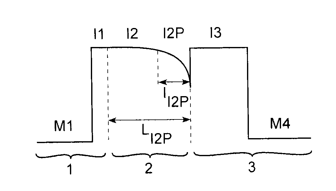
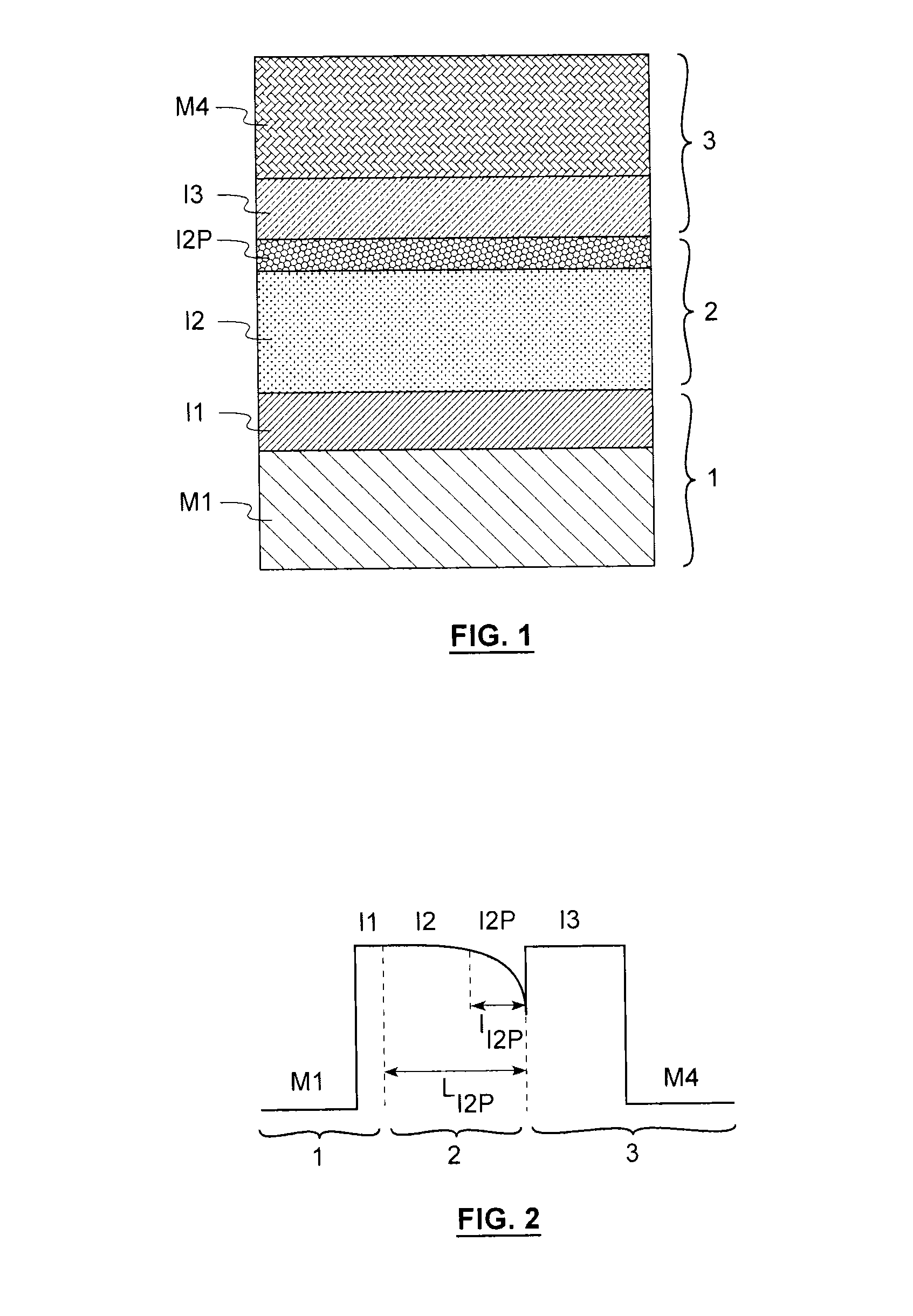
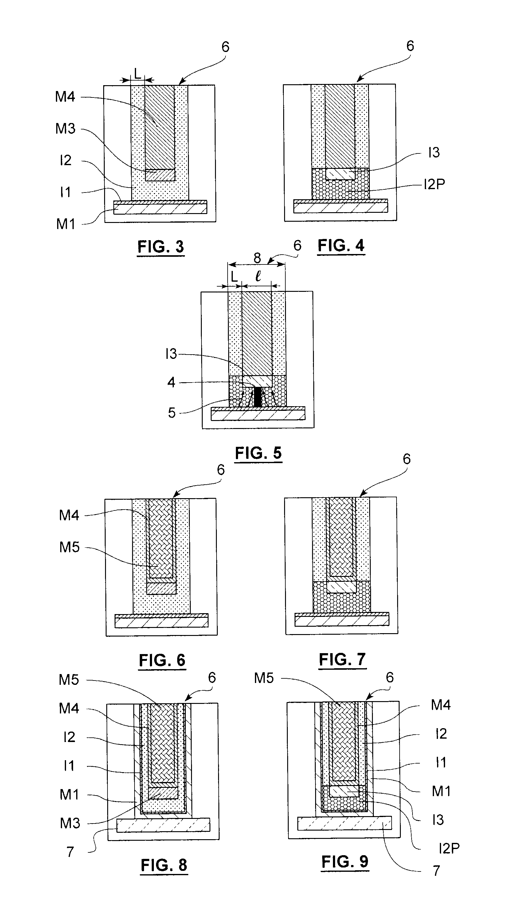
[0125] shown in FIGS. 3 to 7, the stack of the memory cell is partially arranged in the cavity 6. The connection line 7 of the lower level Mi−1 forms the metal layer M1 and possibly its layer of stoichiometric metal oxide I1. This is possible when the connection line 7 is made of Al, Ta, TaN or TiN. The layer of stoichiometric metal oxide I1 is then made of Al2O3, TiO2, TiON, Ta2O5, TaON. The metal layer M1 of the bottom electrode 1 and possibly the layer of stoichiometric metal oxide I1 are arranged outside of and under the cavity. The term under means that the metal layer M1 is present before the formation of the cavity, and the term outside of means that the metal layer M1 is of a length greater than the width of the cavity 6. The cavity 6 comprises from bottom to top, the insulation 2 comprising the layer of stoichiometric metal oxide I2 and the layer of substoichiometric metal oxide I2p forming said oxygen vacancy reservoir layer then the layer of stoichiometric metal oxide I3 ...

second embodiment

[0127] shown in FIGS. 8 and 9, the stack of the memory cell is entirely arranged in the cavity 6. The connection line 7 of the lower level Mi−1 does not form the metal layer M1. This is the case in particular when the connection line 7 is made of a material not adapted to the properties required in order to form a bottom electrode 1. The metal layer M1 of the bottom electrode 1 and possibly the layer of stoichiometric metal oxide I1 are arranged in the cavity 6. In this embodiment, note that the insulation 2 formed at least by the compliant layer of stoichiometric metal oxide I2 guarantees the electrical insulation between the metal layers M1 and M4. The metal layer M1 then plays the role of a barrier intended to limit the diffusion of the material of the connection line 7 in the memory cell.

[0128]The method of manufacturing a memory cell comprises the steps described hereinafter. The formation of a cavity 6 opening onto a connection line 7 of lower level Mi−1. Possibly, the complia...


PUM


Abstract

A resistive non-volatile memory cell including a Metal-Insulation-Metal stack including two electrodes and a multilayer of insulation, placed between the two electrodes, including a thin layer of oxide allowing for a resistive transition and an oxygen vacancy reservoir layer is provided. The stack includes from bottom to top: the bottom electrode including a metal layer, the insulation including a layer of stoichiometric metal oxide and a layer of substoichiometric metal oxide forming the oxygen vacancy reservoir layer, and the top electrode including a layer of metal oxide and a metal layer, such that the oxygen vacancy reservoir layer is inserted between two metal oxide stoichiometric layers.

Description

TECHNICAL FIELD[0001]This invention in general relates to non-volatile memories with resistive elements. It more particularly describes a resistive non-volatile memory cell and the method of manufacture thereof.[0002]The invention will be used possibly in all applications already covered by existing non-volatile memories; in particular, memories of the Flash type. Due to their access time and their writing facility, non-volatile memories with resistive elements can also replace conventional static memories or SRAM (static random access memory).[0003]The invention will also be used to carry out memory structures of the neuromorphic type or for CBRAM memories for the acronym “Conductive Bridge Random Access Memory” or in nanoelectric devices based on the principle of Metal / Insulation transitions also called “Mott insulator”, such as for example Mott selectors, Mott transistors, devices including photo-induced Mott transitions.PRIOR ART[0004]Memories with resistive elements use a mater...

Claims


Application Information

Patent Timeline
IPC IPC(8): H01L45/00H01L27/24
CPCH01L45/08H01L45/1233H01L45/1246H01L45/1253H01L45/165H01L45/147H01L27/2463H01L45/1616H01L45/1641H01L45/146H01L27/101H10N70/821H10N70/24H10N70/841H10N70/826H10N70/043H10N70/023H10N70/8833H10N70/041H10N70/20H10N70/021
Inventor GASSILLOUD, REMYBERNARD, MATHIEU
Owner COMMISSARIAT A LENERGIE ATOMIQUE ET AUX ENERGIES ALTERNATIVES
Why Eureka
Try Eureka