Cable Pair Stabilizer Unit and Method and System for Generating Sealing Current

a stabilizer unit and cable technology, applied in the direction of electrical equipment, substation equipment, interconnection arrangements, etc., can solve the problems of inability to reliably transport dsl services of telephone wires, and difficulty in achieving the effect of preventing oxidation or corrosion of wire splices or connections

Active Publication Date: 2016-07-07
ENGINUITY COMM CORP
View PDF15 Cites 3 Cited by
  • Summary
  • Abstract
  • Description
  • Claims
  • Application Information

AI Technical Summary

Benefits of technology

[0014]A cable pair stabilizer unit generates and injects or sends sealing or wetting current into the Service Provider's telephone cables for DSL (digital subscriber line) service from the customer's premise or residence. The cable pair stabilizer unit utilizes or taps the customer's DSL residential gateway (i.e. modem) power supply adapter to generate the sealing current. By doing so, the cable pair stabilizer unit maintains the telephone cable wire splice continuity from the Service Provider's facility to the Customer Premise's or Residence. This prevents the oxidation or corrosion of wire splices or connections on the telephone cables transporting DSL services, which would otherwise cause errors or loss of service on the DSL service. As a result, the DSL service, which is transported or carried by the telephone cables, is more reliable.

Problems solved by technology

If any of the wire splices or IDC wire connections oxidizes, the telephone wire loses its ability to reliably transport DSL services.
However, the use of two distinct systems for tactical and operations decisions presents numerous inefficiencies, limitations and disadvantages, due to a lack of or limited interaction between the two systems.
When DSL service trouble calls increased, the Service Provider's identified the problem as oxidation or corrosion at telephone cable wire splices or IDC wire connections.
Both attempts were unsuccessful due to space, costs, power consumed, and thermal capabilities, more specifically as follows:
Space: DSL equipment is installed in an outdoor cabinet (called VRAD, Video-Ready Access Device), wherein the VRAD cabinet does not have space to effectively support sealing current generators and injectors.
Cost: The additional cost to provide sealing current generators and injectors on all DSL service would be relatively high.
The added heat from sealing current generators could not adequately be supported.

Method used


Image

  • Cable Pair Stabilizer Unit and Method and System for Generating Sealing Current
  • Cable Pair Stabilizer Unit and Method and System for Generating Sealing Current
  • Cable Pair Stabilizer Unit and Method and System for Generating Sealing Current

Examples


Embodiment Construction

[0041]The following description refers to numerous specific details which are set forth by way of examples to provide a thorough understanding of the relevant method(s) and system(s) disclosed herein. It should be apparent to those skilled in the art that the present disclosure may be practiced without such details. In other instances, well known methods, procedures, components, hardware and / or circuitry have been described at a relatively high-level, without detail, in order to avoid unnecessarily obscuring aspects of the present disclosure. While the description refers by way of example to methods and systems for transport management, it should be understood that the method(s) and system(s) described herein may be used in any situation where logistics is needed or desired.

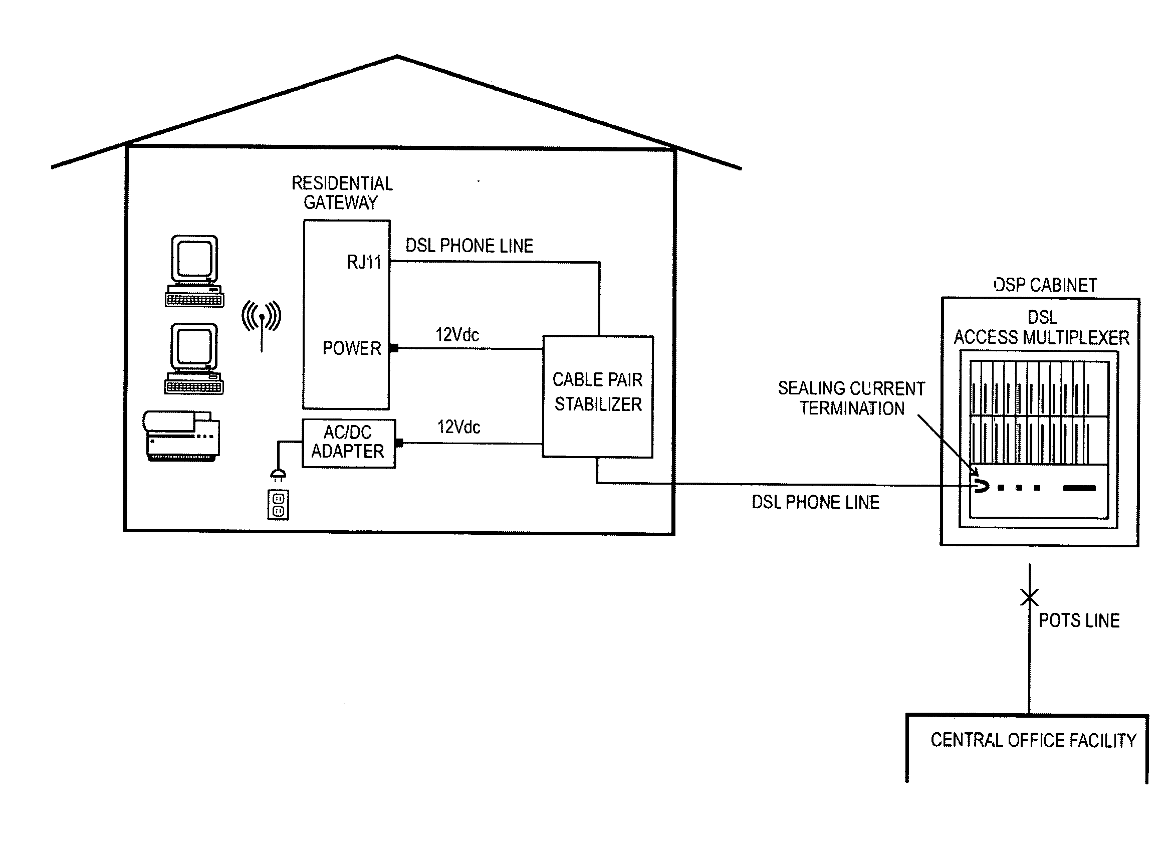
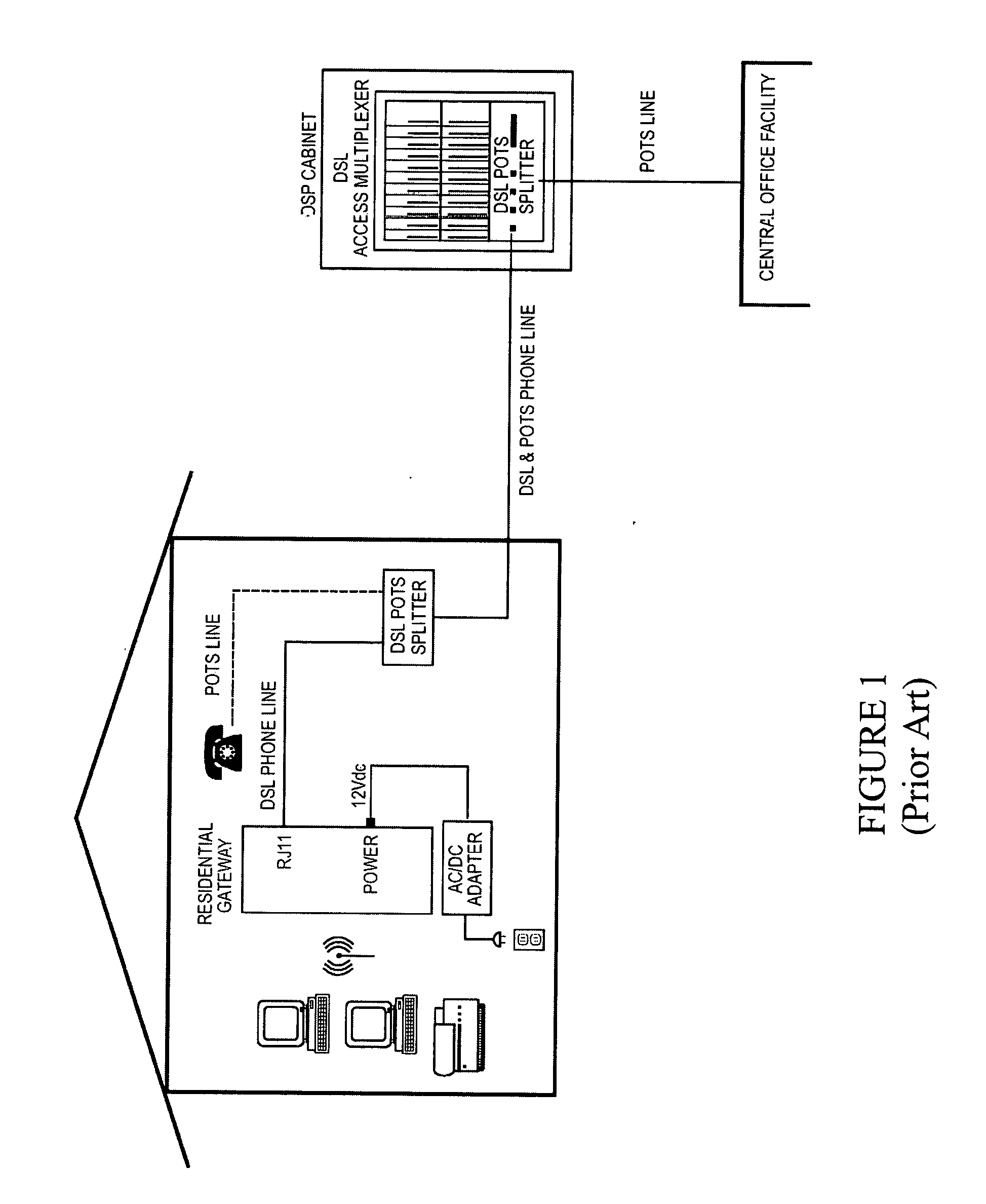
[0042]FIG. 1 is schematic diagram of combined POTS and DSL service delivered by a Central Office to a customer's facility through a DSL OSP equipment cabinet, as is known in the prior art. The current provided by...


PUM


Abstract

The present subject matter relates to one or more devices, systems and/or methods for generating sealing current at a customer's premises or residence and injecting the sealing current into a DSL service provider's telephone cables to prevent the oxidation or corrosion of wire splices or connections on the telephone cables transporting DSL services. A cable pair stabilizer unit is connected at the customer's premises or residence, between the service provider's telephone cables and the customer's residential gateway/modem. The cable pair stabilizer unit comprises circuitry for generating the sealing current and for injecting the sealing current into the service provider's telephone cables transporting DSL services. The cable pair stabilizer unit may be combined with an AC/DC power supply adapter as a single, integrated device. The cable pair stabilizer unit may alternatively be combined with or inside of the Residential Gateway as a single, integrated device.

Description

TECHNICAL FIELD[0001]The exemplary teachings herein pertain to methods and systems for generating sealing current to condition telephone cables, and in particular, to methods and systems which generate and send current into a Service Provider's telephone lines for DSL only or other dry or non-powered broadband service. Specifically, the present disclosure relates to methods and systems, comprising electrical circuitry including a current generator and a current injector, for providing current into the Service Provider's telephone cables to prevent the oxidation or corrosion of wire splices or connections on the telephone cables transporting DSL services, to provide more reliable DSL service.BACKGROUND[0002]For typical DSL service involving one or two wire pairs, the Service Provider would combine POTS (plain old telephone service) and DSL for service deployment. POTS would provide the voice service and the DSL would provide the data and video content. The POTS and DSL services are t...

Claims


Application Information

Patent Timeline
Patent Type & Authority Applications(United States)
IPC IPC(8): H04M1/74H04M19/00H04M3/18
CPCH04M1/745H04M19/001H04M3/18H04M11/062
Inventor IWASAKI, SEANTODD, STEPHEN M.
Owner ENGINUITY COMM CORP
Why Eureka
Try Eureka