Determination system, control signal output system, rehabilitation system, determination method, control signal output method, and recording medium

Active Publication Date: 2016-07-14
PANASONIC INTELLECTUAL PROPERTY MANAGEMENT CO LTD
View PDF1 Cites 10 Cited by
  • Summary
  • Abstract
  • Description
  • Claims
  • Application Information

AI Technical Summary

Benefits of technology

The patent text is saying that they can detect ERD with high accuracy.

Problems solved by technology

However, in the method disclosed in Japanese Unexamined Patent Application Publication No. 2012-217721, ERD is not detected regardless of a user's motor intention in some cases.
ERD detection is a first important step in brain machine interface (BMI) rehabilitation using an electroencephalogram (EEG), and thus it is considered that low ERD detection accuracy may result in a decrease in rehabilitation effect.

Method used


Image

  • Determination system, control signal output system, rehabilitation system, determination method, control signal output method, and recording medium
  • Determination system, control signal output system, rehabilitation system, determination method, control signal output method, and recording medium
  • Determination system, control signal output system, rehabilitation system, determination method, control signal output method, and recording medium

Examples


experiment method

[0036]The test subject was an adult male (36 years old) with no history of cerebral stroke.

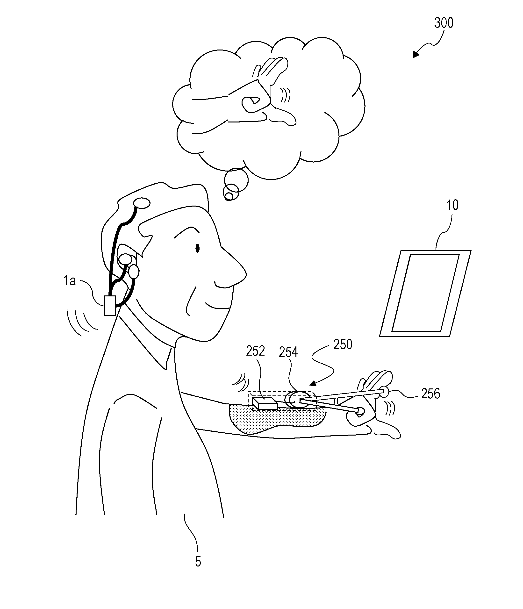
[0037]The test subject was requested to alternately repeat five-second relaxation (referred to as a relax section) and five-second finger extension imaging (referred to as an imaging section) in accordance with a sound stimulation indicating the timing at which tasks are to be changed. An instruction was provided to the test subject to loosen up the whole body as much as possible and relax in the relax section and to image extending fingers slowly for five seconds while keeping the hands squeezed lightly in the imaging section. A right-hand condition of performing finger extension imaging of the right hand and a left-hand condition of performing finger extension imaging of the left hand were provided. Twenty repetitions were regarded as one set, and three sets of experiments were performed for each condition. That is, in a case where a relax section and an imaging section following the relax s...

embodiment

[0085]First, the outline of the ERD measurement system will be described. After that, the configuration and operation of the ERD measurement system including an ERD measurement apparatus will be described.

[0086]FIG. 10 illustrates the configuration of the functional blocks of an ERD measurement system 100 according to the embodiment. The ERD measurement system 100 includes a task indicator 10 and an ERD measurement apparatus 1. The ERD measurement apparatus 1 includes a head electrode 20, an ear hole electrode 30, an EEG signal measurer 50, and an ERD determiner 70. The ERD measurement apparatus 1 is connected to the task indicator 10 in a wired or wireless manner.

Task Indicator 10

[0087]The task indicator 10 is, for example, a tablet terminal. The task indicator 10 is capable of indicating, for example, a text or image message to a user 5 via a display panel, such as a liquid crystal panel. Alternatively, the task indicator 10 is capable of indicating a voice message to the user 5 v...


PUM


Abstract

A determination system includes a head electrode that is located on a left head portion of a user when an intention of the user to move a portion on a right side of a body of the user is detected and that is located on a right head portion of the user when an intention of the user to move a portion on a left side of the body of the user is detected; an ear hole electrode that is located in an ear hole of the user; an electroencephalogram signal measurer that obtains a voltage between the head electrode and the ear hole electrode; and a determiner that determines whether or not a change in the voltage includes the intention to move the portion on the right side of the body or the intention to move the portion on the left side of the body.

Description

BACKGROUND[0001]1. Technical Field[0002]The present disclosure relates to a technique for measuring event-related desynchronization (ERD) in brain waves that is induced by a motor intention.[0003]2. Description of the Related Art[0004]ERD is a phenomenon in which, in the case of intending to perform a movement or actually performing a movement, a voltage strength in the α band and / or a voltage strength in the β band of brain waves at the vicinity of the motor area of the head decreases compared to that in a resting state. It is known that the frequency band in which ERD occurs varies among individuals, that is, ERD may occur only in the α band, only in the β band, or in both of the α and β bands.[0005]Japanese Unexamined Patent Application Publication No. 2012-217721 discloses a rehabilitation apparatus that measures an electroencephalogram (EEG) signal at the vicinity of the motor area corresponding to a target portion of rehabilitation, detects ERD on the basis of a change over ti...

Claims


Application Information

Patent Timeline
IPC IPC(8): A61B5/0478A61H1/02A61B5/00A61B5/296A61B5/374
CPCA61B5/0478A61B5/7275A61H1/0266A61H1/0285A61B5/6817A61B5/369A61B2505/09A61H2201/1207A61H2201/1635A61H2201/164A61H2201/165A61H2201/5007A61H2230/045A61H2230/105G16H20/30G16H40/63A61B5/374A61B5/291
Inventor ADACHI, SHINOBUOZAWA, JUN
Owner PANASONIC INTELLECTUAL PROPERTY MANAGEMENT CO LTD
Why Eureka
Try Eureka