System and Method for 3D Imaging Using a Moving Multiple-Input Multiple-Output (MIMO) Linear Antenna Array

a linear antenna array and moving mimo technology, applied in diversity/multi-antenna systems, instruments, using reradiation, etc., can solve the problems of multiple artifacts, inability to resolve artifacts by a single baseline observation, and the mimo array platform also suffers from several tradeoffs, so as to reduce the ambiguity, save time and expense for data collection, and improve the effect of image resolution

Active Publication Date: 2016-07-14
MITSUBISHI ELECTRIC RES LAB INC
View PDF8 Cites 9 Cited by
  • Summary
  • Abstract
  • Description
  • Claims
  • Application Information

AI Technical Summary

Benefits of technology

[0011]Considering the restriction on the transmit channels, the total number of transmit channels is limited as in a conventional moving MIMO array. However, according to the embodiments of the invention, the subset of transmit antennas and receive antennas are randomly selected. This random selection provides more degrees of freedom in MIMO data collection with improved imaging performance.
[0014]The system provides several advantages over conventional systems. First, the system provides more degrees of freedom in transmitting channels than conventional moving MIMO system. Second, the CS-based method deals with random transmitting channels and motion errors to enable suppression of the ambiguity caused by the velocity variations and location jitter leading to a higher resolution image than those obtained using conventional methods. Third, the system system can perform 3D imaging with fewer channels, which saves time and expense for data collection and provides imaging performance comparable to full channel operation. The reduction of total number channels can increase the size of the scene being imaged or provide a higher resolution.

Problems solved by technology

In addition, this projection may cause several artifacts, such as layover and shadowing.
These artifacts cannot be resolved by a single baseline observation, even using interferometric array imaging techniques.
However, the moving MIMO array platform also suffers from several tradeoffs.
Second, the spatial location of the moving MIMO array are subject to motion errors.
This can cause ambiguity and defocus when left uncompensated.

Method used


Image

  • System and Method for 3D Imaging Using a Moving Multiple-Input Multiple-Output (MIMO) Linear Antenna Array
  • System and Method for 3D Imaging Using a Moving Multiple-Input Multiple-Output (MIMO) Linear Antenna Array
  • System and Method for 3D Imaging Using a Moving Multiple-Input Multiple-Output (MIMO) Linear Antenna Array

Examples


Embodiment Construction

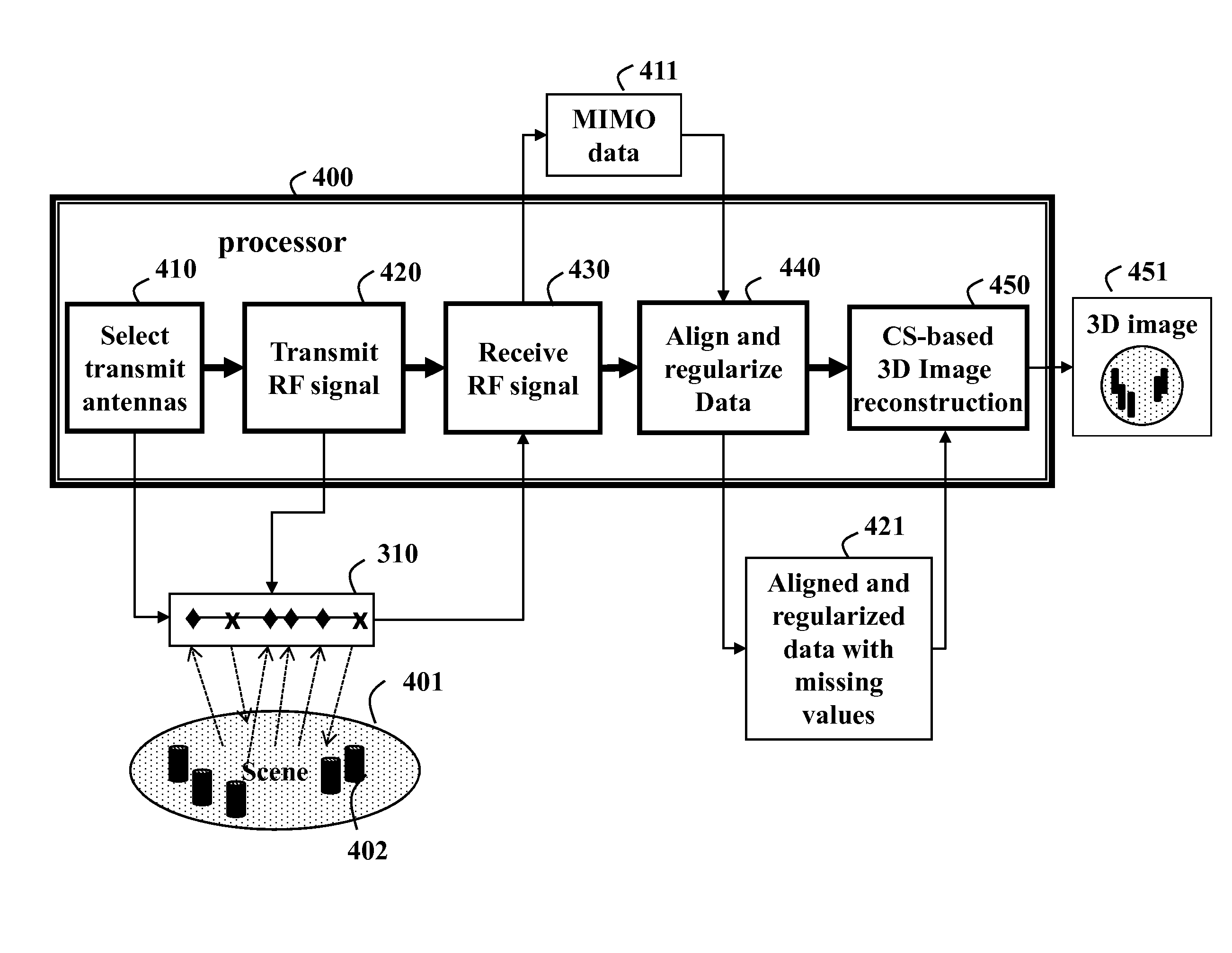
[0019]The embodiments of our invention provide a system and method for 3D imaging using a moving multiple-input multiple-output (MIMO) linear array with a set of antennas. The moving MIMO array uses random transmitting channels and applies compressive sensing (CS)-based imaging to deal with the 3D imaging problem taking into account the random channels and motion errors.

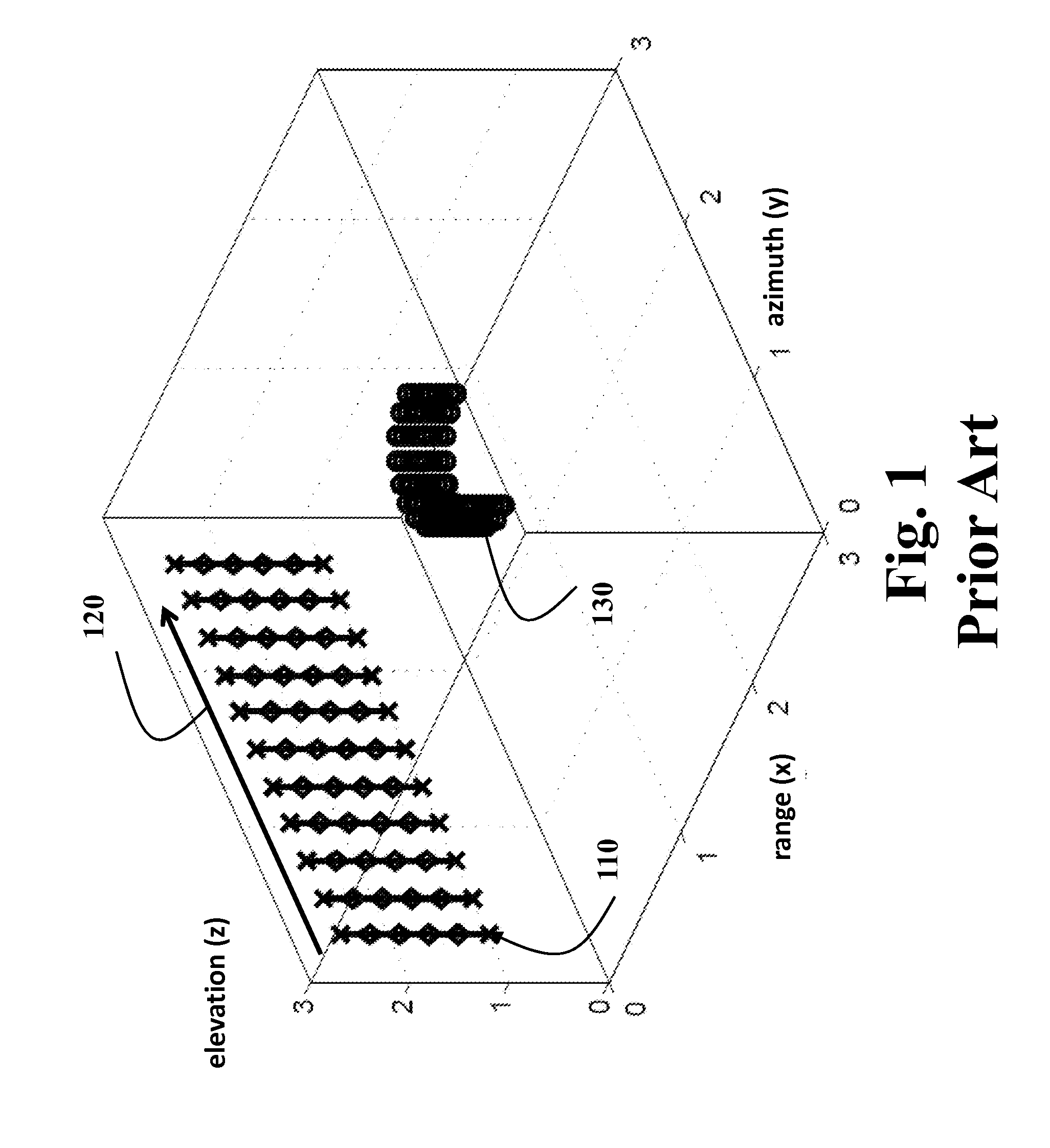
[0020]As shown in FIG. 3, we consider data collected by a moving 320 MIMO array 310. An orientation of the array is parallel to the elevation (z) direction. The array includes subsets of randomly selected transmit (x), and receive (x, ♦) antennas. Note, the transmit antennas can also be used to receive the RF signals after the signals have been transmitted. The array can be subject to random cross-track jitter

[0021]in the azimuth and elevation directions, which are corrected by embodiments of the invention.

[0022]FIG. 4 shows the 3D imaging method according to embodiments of the invention. The method selects 410 subse...


PUM


Abstract

A method generates a three-dimensional (3D) scene image of a scene using a MIMO array including a set of antenna by first selecting a subsets of the antennas as transmit antennas and receive antennas. Radio frequency (RF) signal are transmitted into the scene using the subset of transmit antennas while the MIMO array is moving at a varying velocity. The RF signal are received at the subset of receive antennas as MIMO data, which is aligned and regularized. Then, a compressive sensing (CS)-based reconstruction procedure is applied to the aligned MIMO data to generate the 3D image of the scene.

Description

RELATED APPLICATION[0001]This U.S. Application is related to U.S. application Ser. No. 14 / 202,449, “System and Method for 3D SAR Imaging using Compressive Sensing with Multi-Platform, Multi-Baseline and Multi-PRF Data,” filed by Liu et al. on Mar. 10, 2014, and incorporated herein by reference. That Application also describes 3D SAR imaging using the compressive sensing.FIELD OF THE INVENTION[0002]This invention relates generally to 3D imaging, and more particular to using a MIMO array of antennas, and compressive sensing (CS)-based 3D image reconstruction.BACKGROUND OF THE INVENTION[0003]A conventional single-channel virtual antenna array system makes use of wideband radio frequency (RF) signals and a large synthetic aperture to generate two-dimensional (2D) range-azimuth images. The 2D azimuth images, without any elevation information, are a projection of the 3D scene onto the 2D range-azimuth plane. Therefore, the 3D structure of the scene, such as a 3D terrain, is not preserved ...

Claims


Application Information

Patent Timeline
Patent Type & Authority Applications(United States)
IPC IPC(8): H04B7/04H04B15/00G06T15/00
CPCH04B7/0413H04B15/00G06T15/00G01S13/904H04B7/0479
Inventor LIU, DEHONG
Owner MITSUBISHI ELECTRIC RES LAB INC
Why Eureka
Try Eureka