
Handheld X-Ray Device by Cold Cathode

a cold cathode and x-ray technology, applied in the direction of x-ray tubes, radiation generation arrangements, applications, etc., can solve problems such as unstable curren

Active Publication Date: 2016-07-21
ENERGY RESOURCES INT
View PDF11 Cites 6 Cited by
  • Summary
  • Abstract
  • Description
  • Claims
  • Application Information

AI Technical Summary

Benefits of technology

The present invention is a cold cathode type handheld X-ray device that has the features of being lightweight, low current, and free cooling. The device can maintain a vacuum level even after extended use, ensuring good X-ray photo quality. Additionally, the device allows for easy sighting at a predetermined site for X-ray irradiation.

Problems solved by technology

However, at that current density, the current is not stable.

Method used


Image

  • Handheld X-Ray Device by Cold Cathode
  • Handheld X-Ray Device by Cold Cathode
  • Handheld X-Ray Device by Cold Cathode

Examples


Embodiment Construction

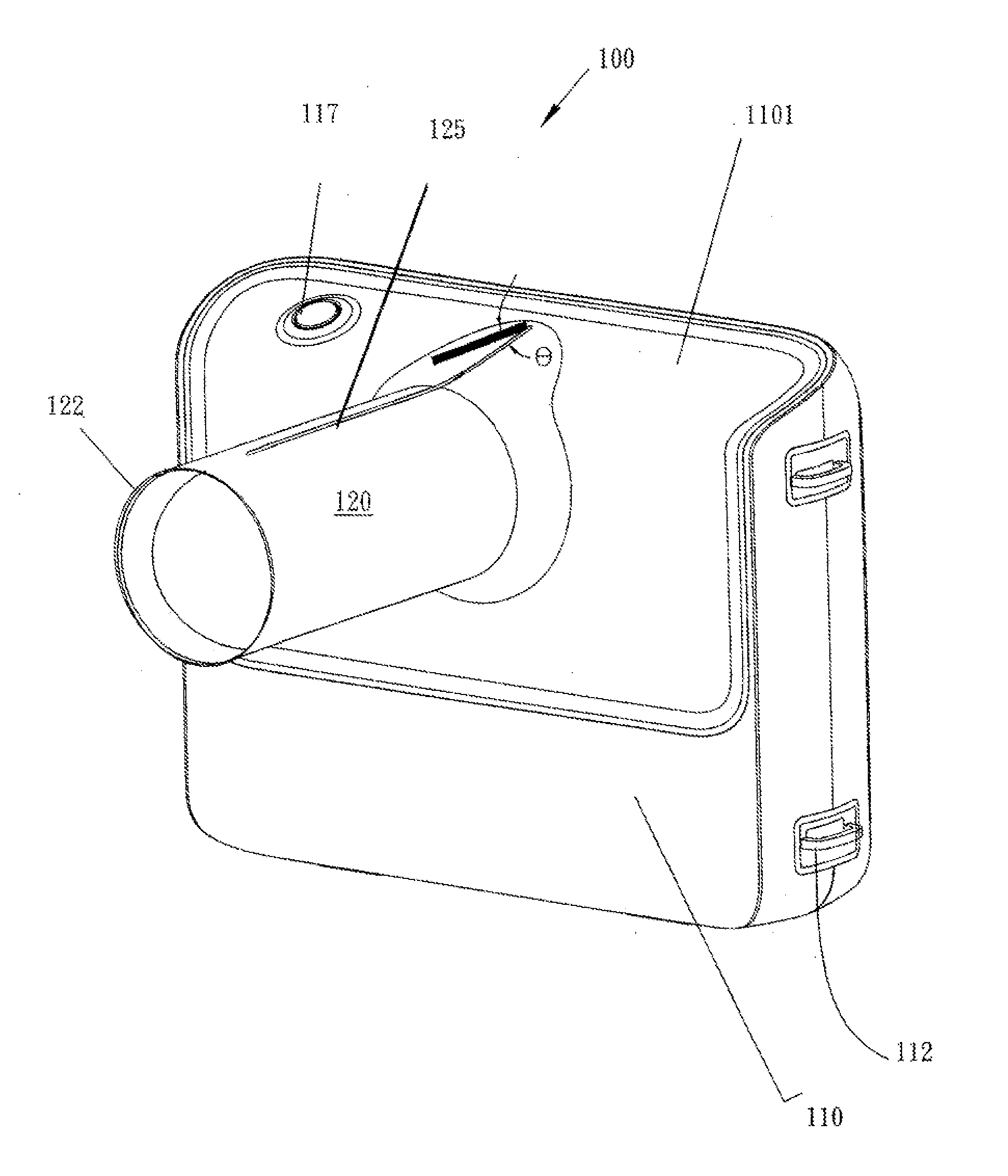
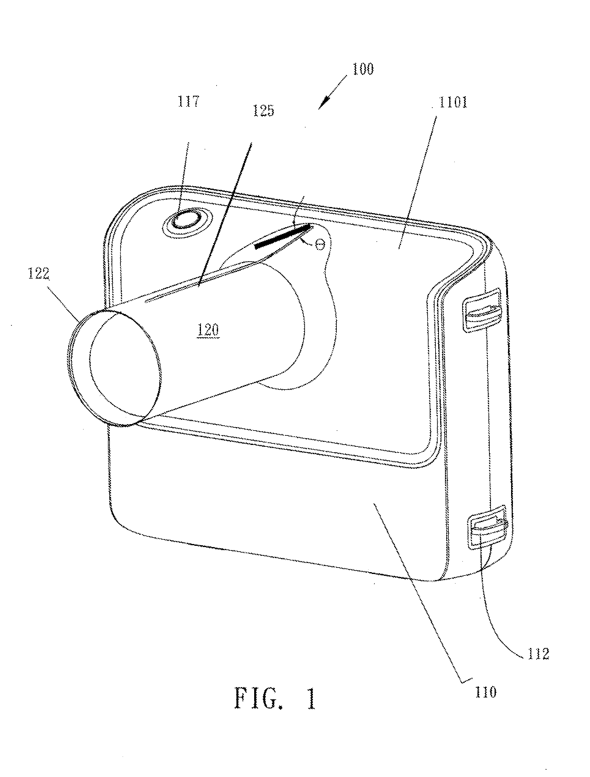
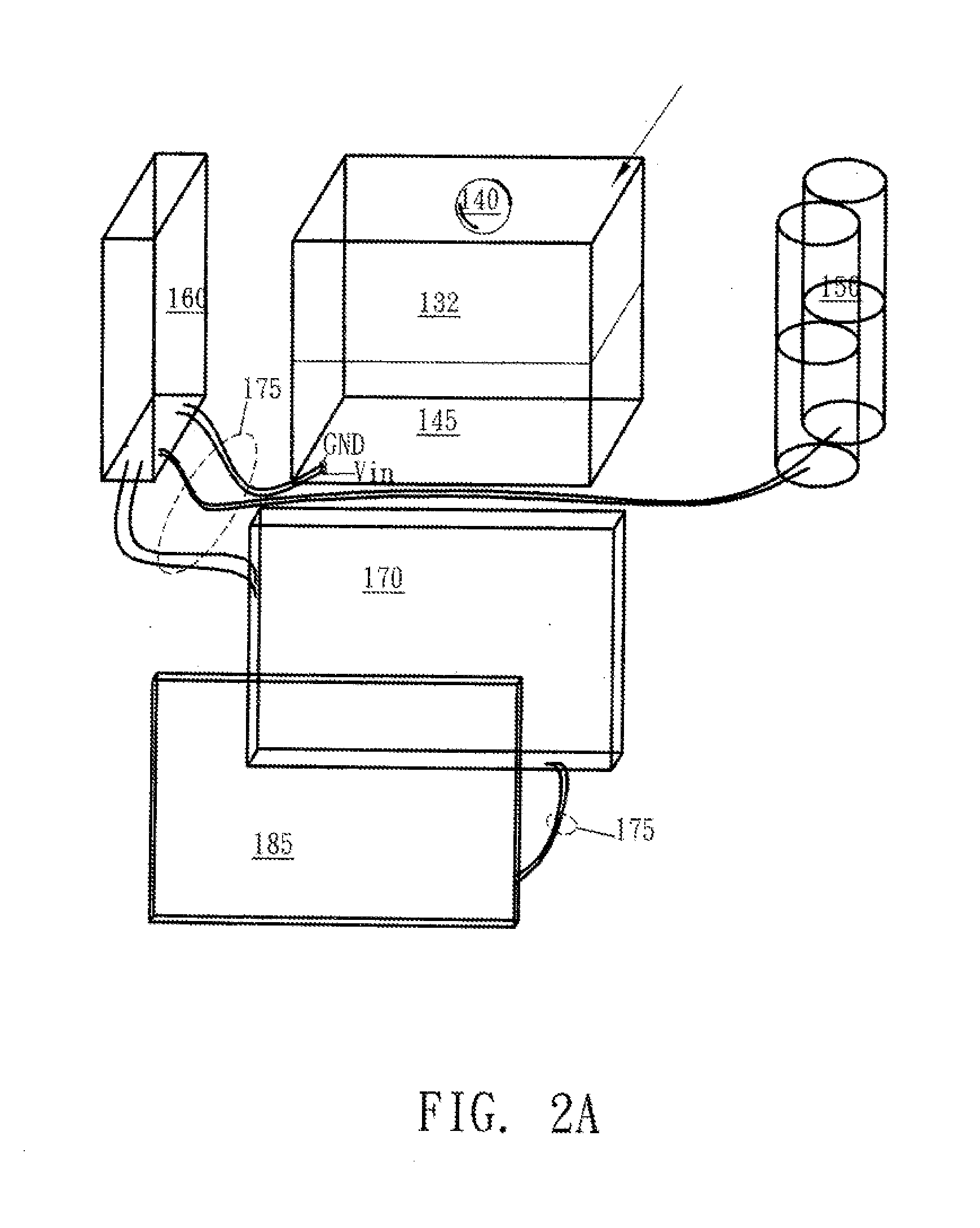
[0020]Referring to FIG. 1 and FIG. 2A, a perspective view of handheld X-ray generator 100 and a schematic view of an internal body 110 of the hand-held X-ray generator, respectively, are shown. In FIG. 1, the handheld X-ray generator body is like a camera. A zoom ring-like object 120 at the front face of the X-ray device body 110 is an X-ray exit. A lead shell 122 is either as a liner inside the zoom ring-like object 120 or as a jacket wrapped the outside surface of the zoom ring-like object 120. A side of the X-ray device body has a buckle provided for a strap there through to relieve the loading of the operator. Inside the X-ray generator body has a rectangular block 130, a battery 150, an oscillation circuit 160 and a control circuit 170. The control circuit 170 including a microprocessor with a LCM driving circuit is connected to a rear panel 180 of the X-ray body 110 as an operator interface. The rear panel 180 including LCD panel 185 and a plurality of signal-indicators and a ...


PUM


Abstract

A handheld X ray device comprises a camera-like X ray generator body having a zoom ring-like object at a front side of the X ray generator body as an exit of X rays and has a collimator section atop a surface of the zoom ring-like object. The camera-like X ray generator body inside has a voltage boosting circuit, an oscillator circuit, a battery, and a control circuit, and a user interface at a real panel of the camera-like X ray generator body. The glass ball-tube is a cold cathode type X-ray generator with a tungsten filament at a periphery of a cold cathode. The voltage boosting circuit, the oscillator circuit, boosting the voltage of the battery up to a predetermined high voltage under controlled of the control circuit assisting by the user interface.

Description

FIELD OF THE INVENTION[0001]The present invention pertains to a cold cathode type handheld X ray device and with a friendly user interface.DESCRIPTION OF THE PRIOR ART[0002]An x-ray generation device with a cold cathode generating field emission electrons is known according to a quantum theory of field electron emission. The basic principle of the field emission electrons is that the electrons of a conductor must have sufficient energy to get a chance to cross the potential energy barrier to the vacuum side when no electric field is applied. When an electric field is applied the energy band is bent, as a result, electrons cross the potential energy barrier to the vacuum side without huge amount of energy. When the applied electric field is increasing, the potential energy barrier by electrons is decreasing and the strength of the derived current is increasing. According to electromagnetic theory, if a charged object has a sharp point, the electric field strength around that point wi...

Claims


Application Information

Patent Timeline
Patent Type & Authority Applications(United States)
IPC IPC(8): A61B6/00H01J35/06
CPCA61B6/462H01J2235/062H01J35/065A61B6/465A61B6/40A61B6/4405A61B6/542A61B6/587
Inventor LAN, WEN-HOWSHIU, YI-TENGHUANG, HUNG-CHIANGCHEN, RENG-SHOLIAO, SHU-FENCHEN, YU-WEI
Owner ENERGY RESOURCES INT
Learn More