Self-tensed and fully spring jacketed optical fiber sensing structure

a technology of optical fiber sensing and self-tensile, which is applied in the direction of force measurement, force measurement, and optical property variation measurement, etc. it can solve the problems of strain hysteresis and loss of accuracy, affecting wavelength drift /sub>b, and being difficult to simulate, so as to prevent elastic deformation and small volume , the effect of light weigh

Active Publication Date: 2016-07-21
JINN HER ENTERPRISE
View PDF1 Cites 6 Cited by
  • Summary
  • Abstract
  • Description
  • Claims
  • Application Information

AI Technical Summary

Benefits of technology

[0022]In the present invention, the initial tension is applied to protect the protective tensile breaking force of the optical fiber placed therein from withstanding external forces. When a steel wire material is coiled into a tight form, the wire can no longer rotate freely, and is thus formed with a certain level of twisting to prevent elastic deformation along the axial direction of the spring. The force that causes the coils to be located tightly closely to one another in the absence of a load is referred to as initial tension. The inventive step of the present invention is to form an optical fiber sensing spring that is self tensed and self jacketed and protected. More specifically, using the initial tension, the optical fiber connected from the FBG is added with the tight and gap-less cylindrical tension coil springs hard as a metal but more flexural and bendable, such that the self jacketed and protected optical fiber sensing spring can be formed.
[0023]An FBG is placed in a spring to form an optical fiber sensing spring. The sensing spring device with the built-in FBG is an important optoelectronic component in waveguide optics, and may be extensively incorporated to applications of optical fiber communication, measuring apparatus control, connection strain measurement and sensing of physical data. Such sensing component may serve as a fundamental cell unit in the research, manufacturing and application of smart structures. The sensing component features advantages of being small in volume, light in weight, high in material strength, strong in geometric toughness, small in optical energy loss, high in transmission speed, and wide in bandwidth, as well as being high temperature and electromagnetic interference resistant. When applied in a highly radioactive environment and extensive use in harsh environments, the present invention provides stable characteristics and durability. Further, to provide critical advantages, in the present invention, one single optical fiber, having a simple structure, can be simultaneously connected in series to multiple measuring points to accurately measure strain physical amounts. Compared to some conventional solutions having complicated strain designs, manufacturing, and installation processes, the present invention is a hugely improved technology for component standardization.

Problems solved by technology

However, because physical properties of an FBG are affected by temperature changes, the wavelength drift ΔλB is also affected.
One common features of all conventional structures is that, a predetermined micro strain, e.g., −2500 μs, needs to be tensed to serve as a future tolerable compression amount after the sensing elements are placed at fixed sensing positions, or else an FBG without tensing may easily generate strain hysteresis and lose its accuracy.
However, from aspects of engineering applications, it is impossible simulate conditions where an enormous object under test in normal use first is compressed, the fiber grating is then fixed, and the measurement is carried out after such compression is released to return to a normal state.
These complicated manufacturing operations are quite costly and need to be standardized as well as simplified to reduce costs and to obtain a more accurate tensing amount.
That is to say, a first drawback of a conventional FBG is that, although a conventional FBG needs to be tensed, there are no standardized and simple tensing carriers.
That is one reason why current FBGs have not yet become standard optical sensing elements.
Further, conventionally, when one FBG is manufactured from one single-mode optical fiber, the structure is usually merely one bare fiber grating having an outer diameter of 0.125 mm (125 μm), and is prone to breakage and cannot withstand lateral pressure.
However, the FBG and an externally connected optical fiber are still likely damaged by external forces, as the conventional fiber grating sensing element fixed on an object under test in FIG. 2.
Such exposed fiber grating without protection, e.g., the region 208 that is an exposed and unprotected fiber grating region, is frequently one of the main reasons causing damage and breakage during the tensing operation, on-site installation process and a measuring process after the installation.
Therefore, a fiber grating without the protection of outer coating material is a second drawback that sets back the standardization of optical fiber sensing elements.
In an on-site environment, when the coated optical fibers connected from two ends of the unprotected fiber grating region and having an outer diameter of 250 μm are further connected to external optical fiber segments, the optical fiber at these two ends is extremely slim and cannot be clearly observed, and are thus likely touched to result in optical power loss or breakage.
The optical fibers externally connected from the two ends of the fiber grating region are unprotected by an appropriate material and are thus easily damaged or broken—such is a third drawback in standardized optical fiber sensing elements.

Method used


Image

  • Self-tensed and fully spring jacketed optical fiber sensing structure
  • Self-tensed and fully spring jacketed optical fiber sensing structure
  • Self-tensed and fully spring jacketed optical fiber sensing structure

Examples


first embodiment

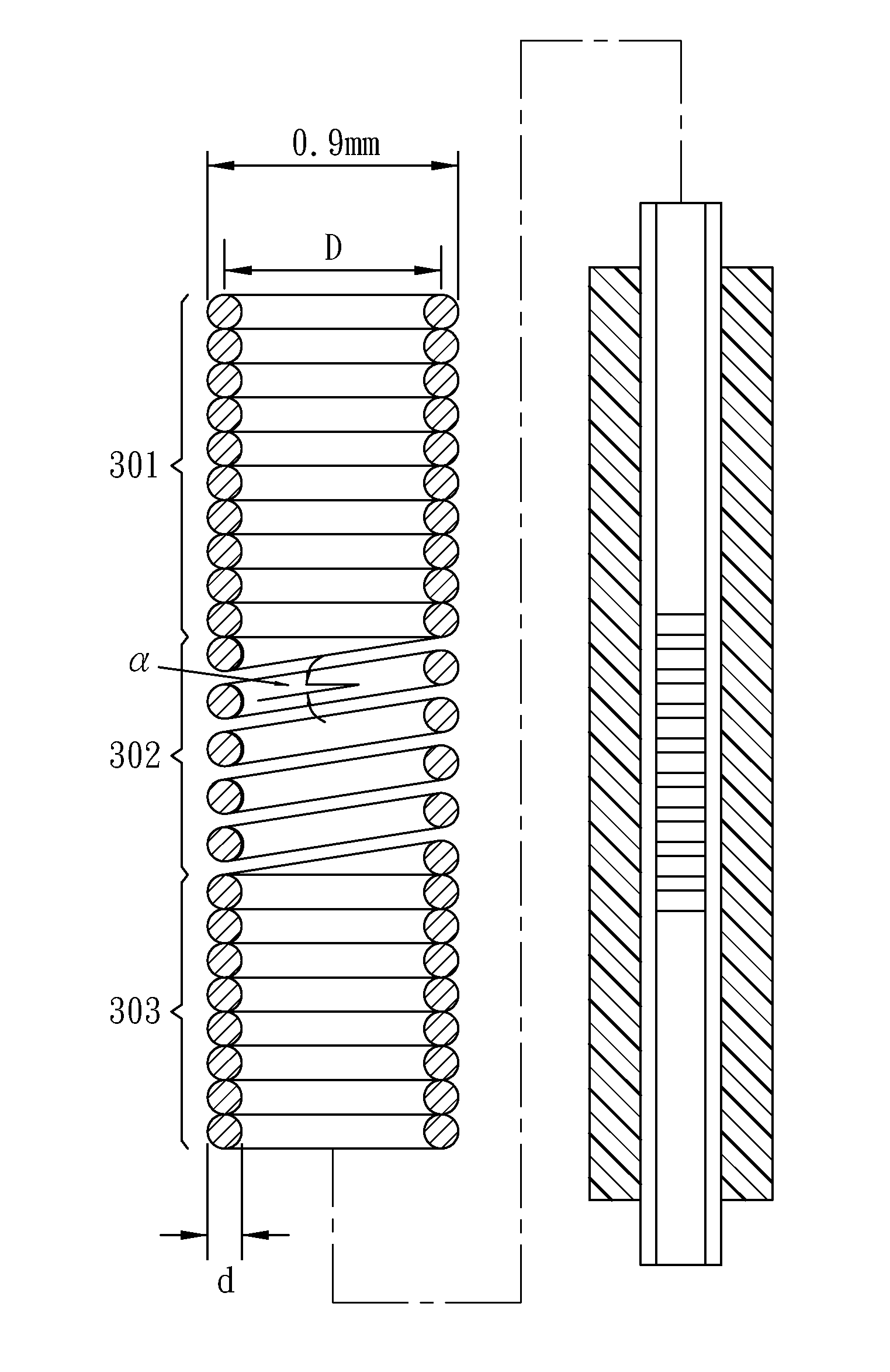
[0038]In this embodiment, as shown in FIG. 3C, a tensed optical fiber sensing spring structure, e.g., the structure shown in FIG. 3B, is installed to a structure under test. The present invention provides an adjustable pre-tensed fiber grating structure, which protects an optical fiber placed therein by a fully spring jacketed length and satisfies a commercial standard of a 0.9 mm outer diameter. Further, the pre-tensed fiber grating structure includes a compression spring 302, which is utilized as a jacket having an outer diameter of 0.9 mm and is pre-compressed to form a stress-strain relationship in a linear elastic region. The compression spring 302 having a predetermined gauge length is compressed and then fixed to two ends of optical fiber and spring pre-tensing fixing and connecting rings, i.e., to positions of the upper connecting ring 308 and the lower connecting ring 309. When the two connecting rings are fixed at a bare optical fiber 201 that is not compressed in an axle ...

second embodiment

[0043]A temperature compensated optical fiber sensing spring structure is provided according to a second embodiment of the present invention.

[0044]As previously described, the physical properties of an FBG are affected by temperature changes to further affect the wavelength drift ΔλB. The wavelength drift caused by the temperature is often represented by ΔλBT. Thus, when applying the FBG as any type of sensing device, multiple sensing devices, placed next to one another or closely connected in series, are utilized to obtain reference values of the wavelength drift ΔλBT caused by the same temperature change. The wavelength drift ΔλBT caused by the same temperature change region is then deducted to perform a function of temperature compensation and correction. In the second embodiment, a temperature compensated optical fiber sensing spring structure is as shown in FIG. 8. 801 represents a sensing spring carrier rivet. In FIG. 8, the two sets of optical fiber sensing springs arranged n...


PUM


Abstract

An optical fiber sensing spring of the present invention includes a longer cylindrical tension coil spring, a shorter cylindrical compression coil spring and a longer cylindrical tension coil spring that are connected in series to form a spring having the same inner and outer diameters. A single-mode optical fiber manufactured with a long section of fiber grating is placed in the manufactured spring. This section of the fiber grating is tensed to two ends of the cylindrical compression coil spring having a predetermined gauge length, and the force applied is released. A pre-tensing method for providing a maximum tolerable compression strain and manufacturing technology for this sensing element are then achieved. Thus, the self-tensed optical fiber sensing spring structure satisfies a standard 0.9 mm outer diameter, is fully spring jacketed by the full spring jacketing and protection layer, and forms a linear stress-strain relationship in an elasticity stretched elastic region.

Description

FIELD OF THE INVENTION[0001]The present invention relates to a technology of a strain predetermining and strain measuring device based on physical properties of an optical fiber sensing spring and particularly, to a technology that predetermines a strain sensing range within an effective axial stress sensing region of a sensing element and accurately measures strain.BACKGROUND OF THE INVENTION[0002]In the prior art, a fiber grating is formed by an optical fiber to serve an optical fiber sensing function. According to different characteristics, shapes, uses and purposes of measuring points, a fiber grating may made into various structures to form excellent strain sensing elements that accurately measure strain values by means of an externally connected optical wavelength scanning apparatus. A fiber grating is also referred to as a Fiber Bragg Grating (to be referred to as an FBG), which may serve as a fiber grating sensor. In an FBG, the optical fiber is exposed by using a coherent l...

Claims


Application Information

Patent Timeline
Patent Type & Authority Applications(United States)
IPC IPC(8): G01B11/16
CPCG01B11/18
Inventor TSAI, YUNG-YUYANG, CHUN-CHU
Owner JINN HER ENTERPRISE
Why Eureka
Try Eureka