
Damping force generation device for vehicle

a generation device and damping force technology, which is applied in mechanical equipment, shock absorbers, transportation and packaging, etc., can solve the problems of excessive damping force, radio noise is liable to be generated, and the installation space of electrostatic eliminators is also required, so as to facilitate the fixation and enhance the diselectrification effect, the effect of efficient movemen

Active Publication Date: 2016-07-28
TOYOTA JIDOSHA KK
View PDF0 Cites 26 Cited by
  • Summary
  • Abstract
  • Description
  • Claims
  • Application Information

AI Technical Summary

Benefits of technology

The present invention aims to prevent excessive charging of electric charge to oil in a shock absorber, which can increase oil viscosity and result in a strong damping force. This can cause damage to the shock absorber and impact its performance. The technical effect of this invention is to prevent excessive charging of electric charge to oil, which can reduce oil viscosity and improve the performance of the shock absorber.

Problems solved by technology

Radio noise is liable to be generated when the electric charge is charged to the vehicle body or the like.
The related-art electrostatic eliminator as disclosed in Japanese Patent Application Laid-open No. 2009-181694 has a complicated structure, and hence the electrostatic eliminator is required to be connected to the minus terminal of the battery and the vehicle body through the conductive wires, with the result that an installation space for the electrostatic eliminator is also required.
As a result, the viscosity of the oil is increased so that damping forces are liable to become excessive.
The related-art electrostatic eliminator as disclosed in Japanese Patent Application Laid-open No. 2009-181694 is restricted in terms of an installation location, and cannot thus be installed at a location for effectively reducing the electric charge that is charged to the oil in the shock absorbers.
Therefore, the excessive damping force resulting from the increase in the viscosity of the oil caused by the charging of the electric charge cannot be effectively prevented by the related-art electrostatic eliminator.

Method used


Image

  • Damping force generation device for vehicle
  • Damping force generation device for vehicle
  • Damping force generation device for vehicle

Examples


first embodiment

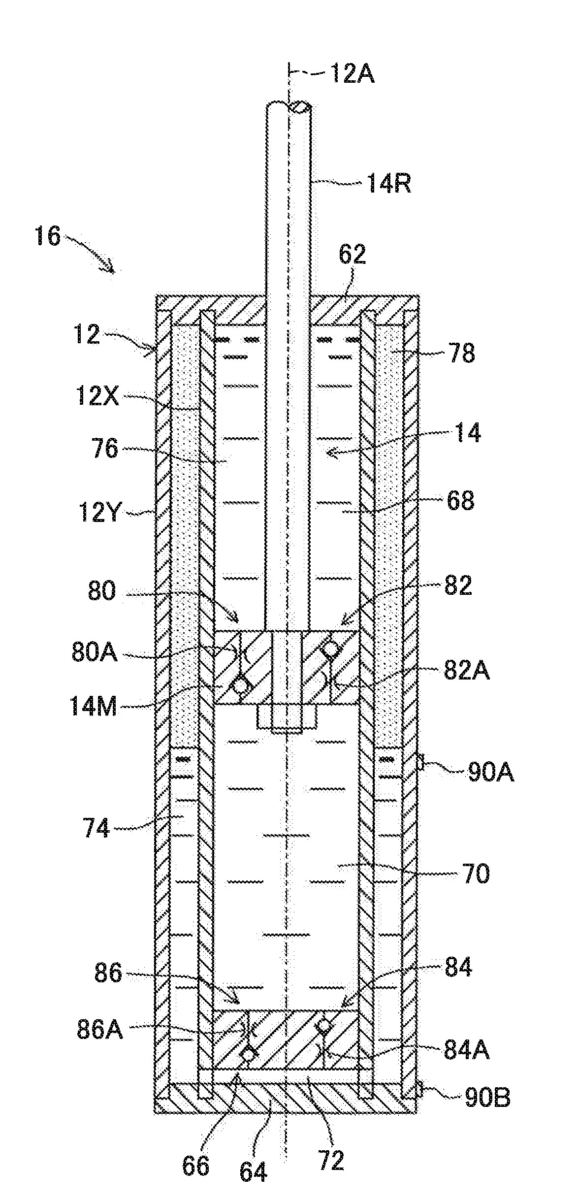
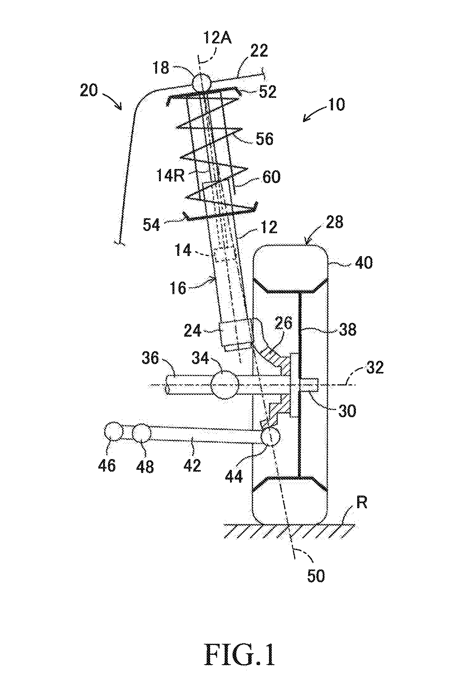
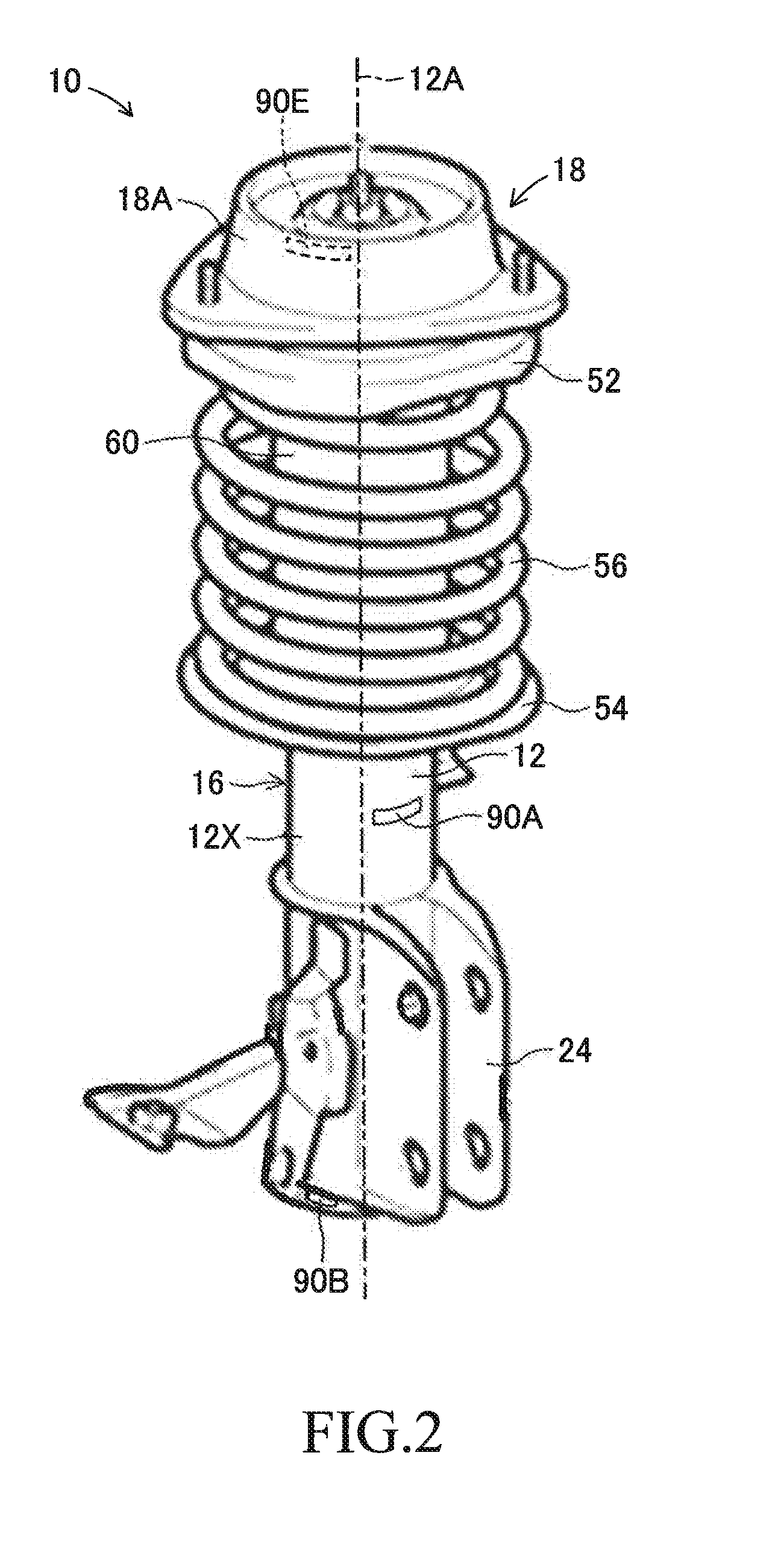
[0043]FIG. 1 is a schematic view for illustrating a damping force generation device 10 according to a first embodiment of the present invention applied to a MacPherson strut front suspension when viewed from the rear of a vehicle. FIG. 2 is a perspective view of the damping force generation device 10 illustrated in FIG. 1. FIG. 3 is an exploded perspective view of the damping force generation device 10 illustrated in FIG. 1.

[0044]In FIG. 1 to FIG. 3, the damping force generation device 10 includes a shock absorber 16 including a cylinder12 and a piston 14. The piston 14 is fitted to the cylinder 12 so as to be reciprocally movable with respect to the cylinder 12 along an axis 12A. The cylinder 12 and the piston 14 are made of a metal such as steel. A rod part 14R of the piston 14 extends upward through a top end of the cylinder 12. Note that, members described below are made of a conductive metal such as steel except for members whose forming materials are particularly described. Me...

second embodiment

[0077]FIG. 8 is a partial cross sectional view for illustrating a main part of a damping force generation device 10 according to a second embodiment of the present invention applied to the MacPherson strut front suspension when viewed from the rear of the vehicle. FIG. 9 is a cross sectional view for illustrating an overview of a mono-tube shock absorber illustrated in FIG. 8. Note that, in FIG. 8 and FIG. 9, members corresponding to the members illustrated in FIG. 1 to FIG. 4 are denoted by the same reference symbols as those placed on FIG. 1 to FIG. 4.

[0078]The shock absorber 16 according to the second embodiment is an input separation type shock absorber. The upper support 18 includes an inner tubular member 18B, an outer tubular member 18C, and a rubber bush 18D filled between the inner tubular member 18B and the outer tubular member 18C. A stopper ring 100 is fitted to a distal end of the rod part 14R under a state in which the stopper ring 100 abuts against the shoulder part 1...

third embodiment

[0091]FIG. 10 and FIG. 11 are enlarged cross sectional views for illustrating an overview of a shock absorber 16 in a damping force generation device 10 according to a third embodiment of the present invention constructed as a twin-tube variable damping force shock absorber. In particular, FIG. 10 is a view for illustrating the expansion stroke, and FIG. 11 is a view for illustrating the contraction stroke. The shock absorber 16 according to the third embodiment is constructed as a so-called uniflow type variable damping force shock absorber.

[0092]As illustrated in FIG. 10 and FIG. 11, between the inner cylinder 12X and the outer cylinder 12Y, a metal intermediate cylinder 12M extending along the axis 12A coaxially with the inner cylinder 12X and the outer cylinder 12Y is arranged. The intermediate cylinder 12M is radially separated from the inner cylinder 12X and the outer cylinder 12Y, and is fixed to the inner cylinder 12X by welding or the like at a top end and a bottom end, to ...


PUM


Abstract

A damping force generation device for a vehicle includes a shock absorber including a cylinder and a piston. The shock absorber is coupled to a vehicle body, a wheel carrier, and the like at a rod part of the piston and the cylinder, respectively, and is configured to generate a damping force due to a flow resistance when oil passes through an orifice formed in the piston. Each of self-discharge type charge eliminators is fixed to a surface of a specific member being at least one of a component of the shock absorber or an auxiliary member connected to the component. The charge eliminator reduces positive electric charge that is charged to the specific member, to thereby reduce a charge amount of the oil.

Description

BACKGROUND OF THE INVENTION[0001]1. Field of the Invention[0002]The present invention relates to a damping force generation device for a vehicle, and more particularly, to a damping force generation device including a shock absorber.[0003]2. Description of the Related Art[0004]When a vehicle such as an automobile travels, static electricity is generated in the vehicle due to the flow of air in a state in which the air is brought into friction contact with the vehicle. Static electricity is also generated when each portion of a tire is repeatedly brought into contact with a road surface and separated therefrom along with the rotation of a wheel, when components in an engine, a brake device, or the like move relatively under a contact state, and the like.[0005]The vehicle is substantially electrically insulated from the ground due to a tire having low conductivity, and hence electric charge (in general, positive electric charge) is charged to a vehicle body or the like when static ele...

Claims


Application Information

Patent Timeline
IPC IPC(8): B60G13/08B60R16/06F16F9/32
CPCB60G13/08F16F9/3207B60G2206/41B60G2202/24B60R16/06F16F9/38H05F3/06B60G15/062F16F9/46F16F9/54F16F9/3235F16F2230/0023F16F2230/10
Inventor TANAHASHI, TOSHIOKANEHARA, YOJIYAMADA, KOSHI
Owner TOYOTA JIDOSHA KK
Learn More