High pressure ratio twin spool industrial gas turbine engine

a gas turbine engine and high pressure ratio technology, applied in the direction of engines, efficient propulsion technologies, mechanical devices, etc., can solve the problems of limited inlet temperature of the turbine to the material properties of the turbine, low component (compressor and turbine), and limit the low power limit at which the engine is allowed to operate. , to achieve the effect of reducing the temperature of compressed air and high engine efficiency

Inactive Publication Date: 2016-07-28
FLORIDA TURBINE TECH
View PDF21 Cites 24 Cited by
  • Summary
  • Abstract
  • Description
  • Claims
  • Application Information

AI Technical Summary

Benefits of technology

The patent describes a twin spool gas turbine engine used for power production that has a high pressure spool and a low pressure spool that can be operated independently. This allows for a high efficiency in the engine with a low turn-down ratio. The high pressure spool is connected to an electric generator and operates at a constant speed. The low pressure spool is driven by turbine exhaust from the high pressure spool and includes variable inlet guide vanes to regulate its speed. Compressed air from the low pressure spool is supplied to the high pressure spool and used to cool the air before it reaches the compressor. An interstage cooler can also be used to decrease the temperature of the compressed air. Additionally, the turbine exhaust from both spools can be directed into a heat recovery steam generator to produce steam and power a steam turbine to further increase efficiency of the power plant. The low pressure spool design allows for a variety of different sizes of prior art single spool engines to be retrofitted by simply changing the size and pressure ratio of the low pressure spool.

Problems solved by technology

However, the turbine inlet temperature is limited to the material properties of the turbine, especially the first stage vanes and blades, and an amount of cooling capability for these first stage airfoils.
These designs suffer from several major issues that include low component (compressor and turbine) performance for high cycle pressure ratios or low part load component efficiencies or high CO (carbon monoxide) emissions at part load when equipped with low NOx combustors which limit the low power limit at which they are allowed to operate (referred to as the turn-down ratio).
The configuration of FIG. 12 IGT engine is the most common for electric power generation and is limited by non-optimal shaft speeds for achieving high component efficiencies at high pressure ratios.
The mass flow inlet and exit capacities are limited structurally by AN2 (last stage blade stress) and tip speeds that limit inlet and exit diameters due to high tip speed induced Mach # losses in the flow.
The small blade height at a relatively high radius gives high losses due to clearance and leakage affects.
This drives the high pressure shaft flow path to a higher radius relative to what might otherwise be feasible, which thereby reduces the speed of the high pressure rotor, creating smaller radius blades which reduce the efficiency of the high pressure spool. FIG. 13 arrangement is similarly limited in achieving high component efficiencies at high pressure ratios as FIG. 12 since the entire compressor is on one shaft.
The FIG. 14 arrangement is similarly limited as the FIG. 12 arrangement in flow inlet mass flow reduction since the low pressure compressor runs the constant speed of the generator.
The FIG. 15 arrangement is the most efficient option of the current configurations for IGT engines, but is not optimal because the low spool shaft 6 rotates within the high spool shaft 5, and thus a further reduction in the high spool radius cannot be achieved.
In addition, if the speed of the low spool shaft 6 is reduced to reduce inlet mass flow, there is a mismatch of angle entering the LPT (Low Pressure Turbine) from the HPT (High Pressure Turbine) and mismatch of the flow angle exiting the LPT and entering the PT (Power Turbine) leading to inefficient turbine performance at part load.

Method used


Image

  • High pressure ratio twin spool industrial gas turbine engine
  • High pressure ratio twin spool industrial gas turbine engine
  • High pressure ratio twin spool industrial gas turbine engine

Examples


first embodiment

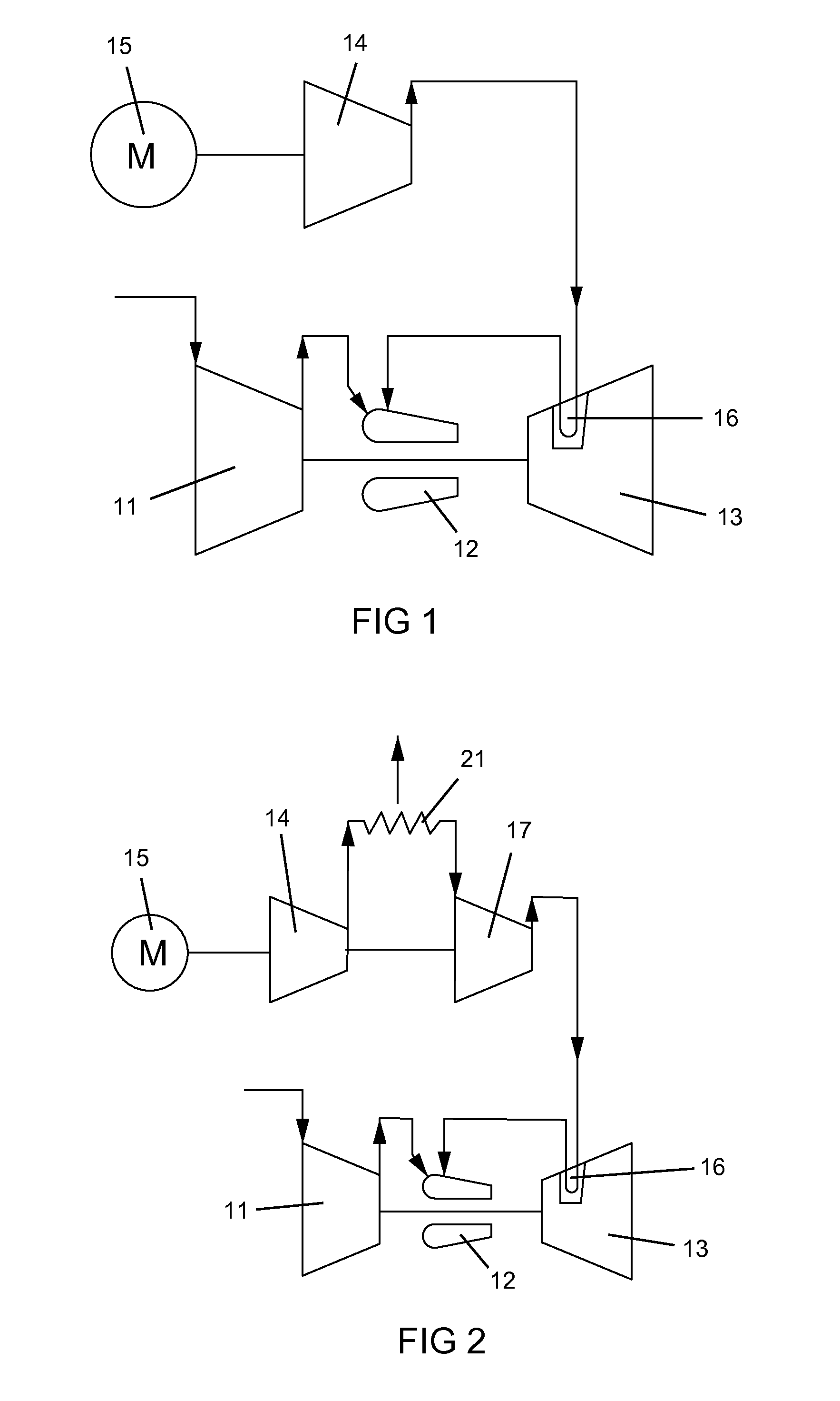
[0035]The present invention is a gas turbine engine with cooling of the turbine stator vanes. FIG. 1 shows the present invention with a gas turbine engine having a compressor 11, a combustor 12 and a turbine 13 in which the compressor 11 and the turbine 13 are connected together by a rotor shaft. The turbine 13 has a first stage of stator vanes 16 that are cooled. The compressor 11 compresses air that is then burned with a fuel in the combustor 12 to produce a hot gas stream that is passed through the turbine 13. A second compressor 14 is driven by a motor 15 to compress air at a higher pressure than from the first compressor 11. The higher compressed air is then passed through the stator vanes 16 in the turbine 13 for cooling, and the heated cooling air is then passed into the combustor 12 to be combined with the fuel and the compressed air from the first compressor 11.

[0036]The second compressor 14 produces high pressure compressed air for cooling of the stator vanes 16 such that ...

second embodiment

[0037]FIG. 2 shows the present invention in which the two stage (14, 17) compressor (i.e.: a multiple stage axial flow compressor) includes an inter-stage cooler 21 to cool the compressed air in order to increase the performance of the two stage compressor (14, 17). The compressed air from the two stage compressor (14, 17) and the inter-stage cooler 21 is then used to cool the stator vanes 16 which is then discharged into the combustor 12. The two stage compressor (14, 17) with the inter-stage cooler 21 produces a higher pressure cooling air than the first compressor 11 so that enough pressure remains after cooling of the stator vanes 16 to be discharged into the combustor 12.

third embodiment

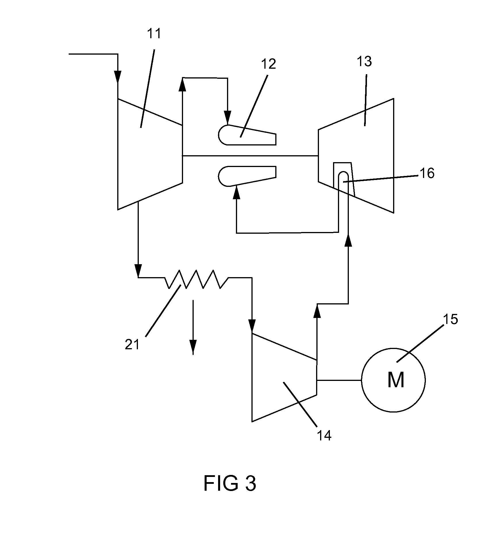
[0038]FIG. 3 shows the present invention where the cooling air for the stator vanes 16 is bled off from a later stage (after the first stage) of the first compressor 11, passed through an inter-stage cooler 21, and then enters a second compressor 14 to be increased in pressure. The higher pressure air from the second compressor 14 is then passed through the stator vanes 16 for cooling, and then discharged into the combustor 12.

[0039]In the three embodiments, the first or main compressor 11 provides approximately around 80% of the required air for the combustor 12. The second compressor 14 produces the remaining 20% for the combustor 12. In one industrial gas turbine engine studied, the first or main compressor 11 has a pressure ratio of 30 (that is, the outlet pressure is 30 times that of the inlet) while the second compressor 14 has a pressure ratio of 40 (that is, the outlet pressure is 40 times that of the inlet).

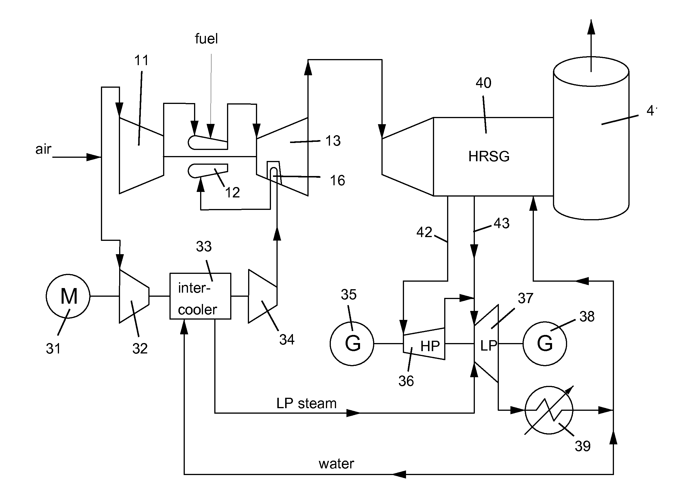
[0040]FIG. 4 shows another embodiment of the present invention with...


PUM


Abstract

An industrial gas turbine engine for electrical power production includes a high pressure spool and a low pressure spool in which the low pressure spool can be operated from full power mode to zero power mode when completely shut off, where the low pressure spool is operated at high electrical demand to supply compressed air to the high pressure compressor of the high pressure spool, and where turbine exhaust is used to drive a second electric generator from steam produced in a heat recovery steam generator. The power plant can operate at 25% of peak load while keeping the unused parts of the power plant hot for easy restart when high power output is required.

Description

FIELD OF THE INVENTION[0001]The present invention relates generally to an industrial gas turbine engine, and more specifically to a twin spool industrial gas turbine engine with a low pressure spool that can be operated independently of the high pressure spool.BACKGROUND OF THE INVENTION[0002]In a gas turbine engine, such as a large frame heavy-duty industrial gas turbine (IGT) engine, a hot gas stream generated in a combustor is passed through a turbine to produce mechanical work. The turbine includes one or more rows or stages of stator vanes and rotor blades that react with the hot gas stream in a progressively decreasing temperature. The efficiency of the turbine, and therefore the engine, can be increased by passing a higher temperature gas stream into the turbine. However, the turbine inlet temperature is limited to the material properties of the turbine, especially the first stage vanes and blades, and an amount of cooling capability for these first stage airfoils.[0003]In an...

Claims


Application Information

Patent Timeline
Patent Type & Authority Applications(United States)
IPC IPC(8): F02C3/34H02K7/18F01D15/10F02C3/107F02C7/36
CPCF02C3/34F02C3/107F02C7/36F05D2220/76H02K7/1823F05D2220/32F01D15/10Y02E20/16F02C7/143F01K23/10Y02T50/60
Inventor BROSTMEYER, JOSEPH D.CEJKA, JUSTIN T.JONES, RUSSELL B.
Owner FLORIDA TURBINE TECH
Why Eureka
Try Eureka