Electromagnetic Relief Valve for Turbocharger
- Summary
- Abstract
- Description
- Claims
- Application Information
AI Technical Summary
Benefits of technology
Problems solved by technology
Method used
Image
Examples
Embodiment Construction
[0031]The technical scheme of the embodiments of the invention will be described clearly and completely in combination with the drawings of the embodiments of the invention.
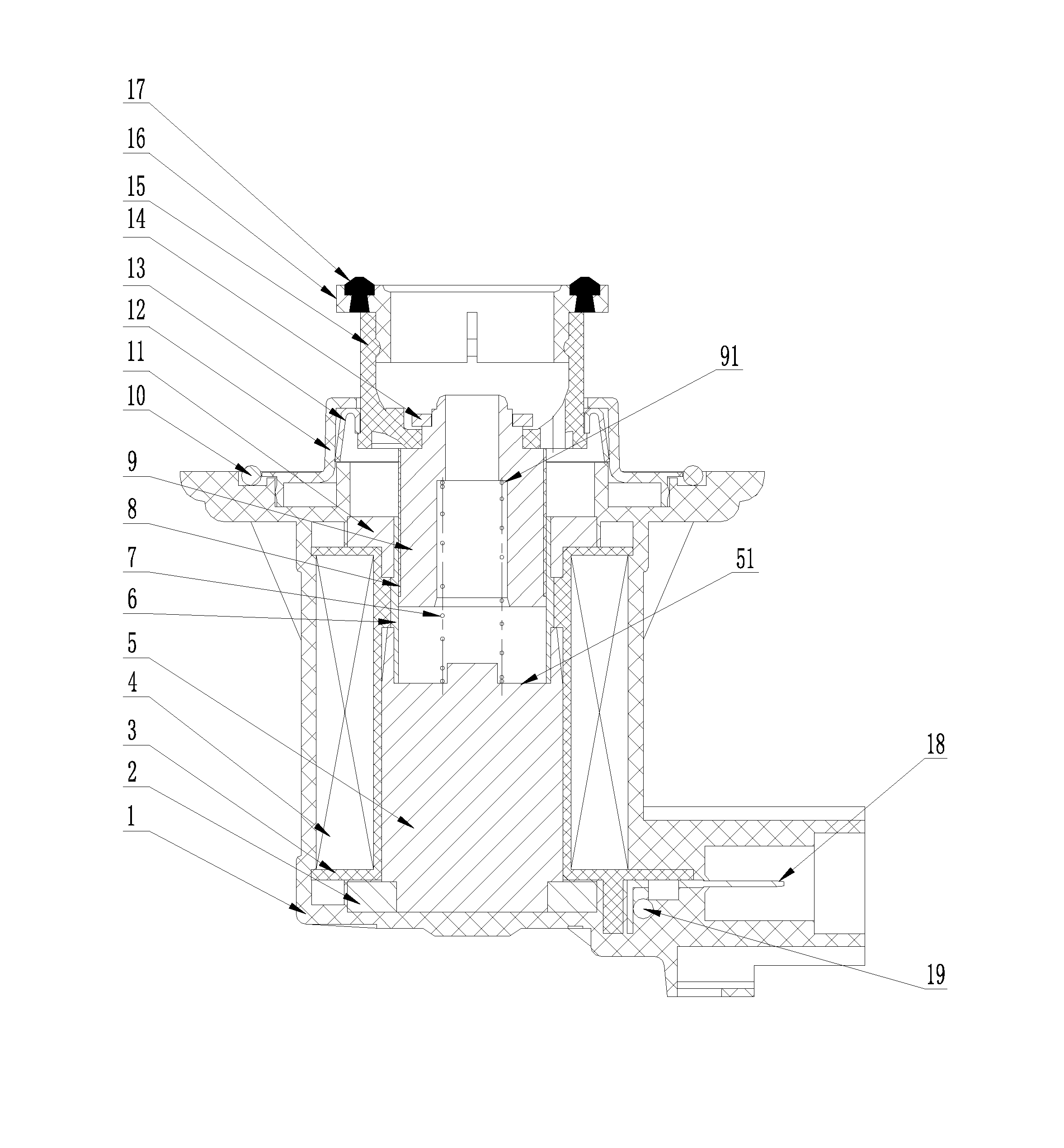
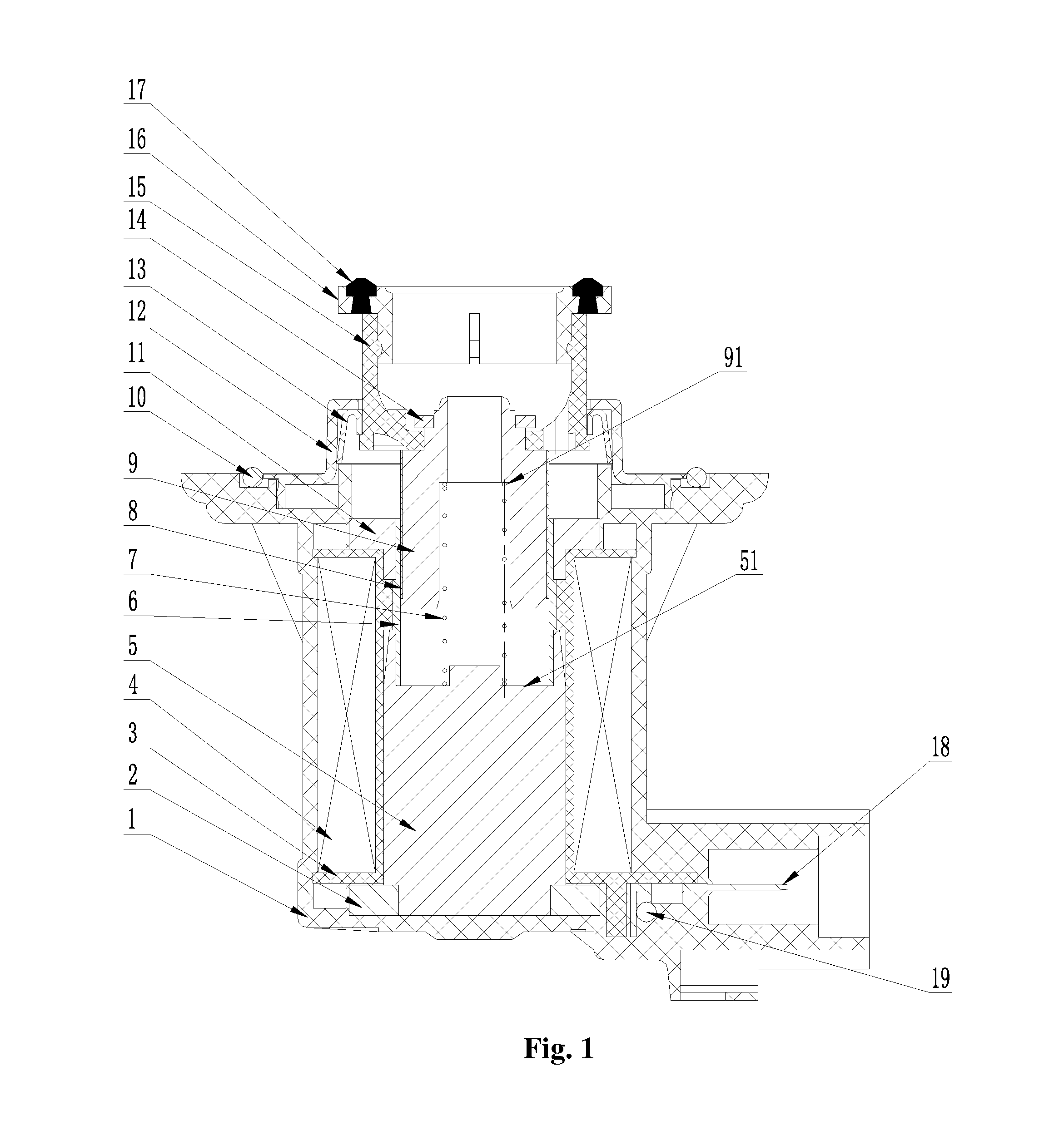
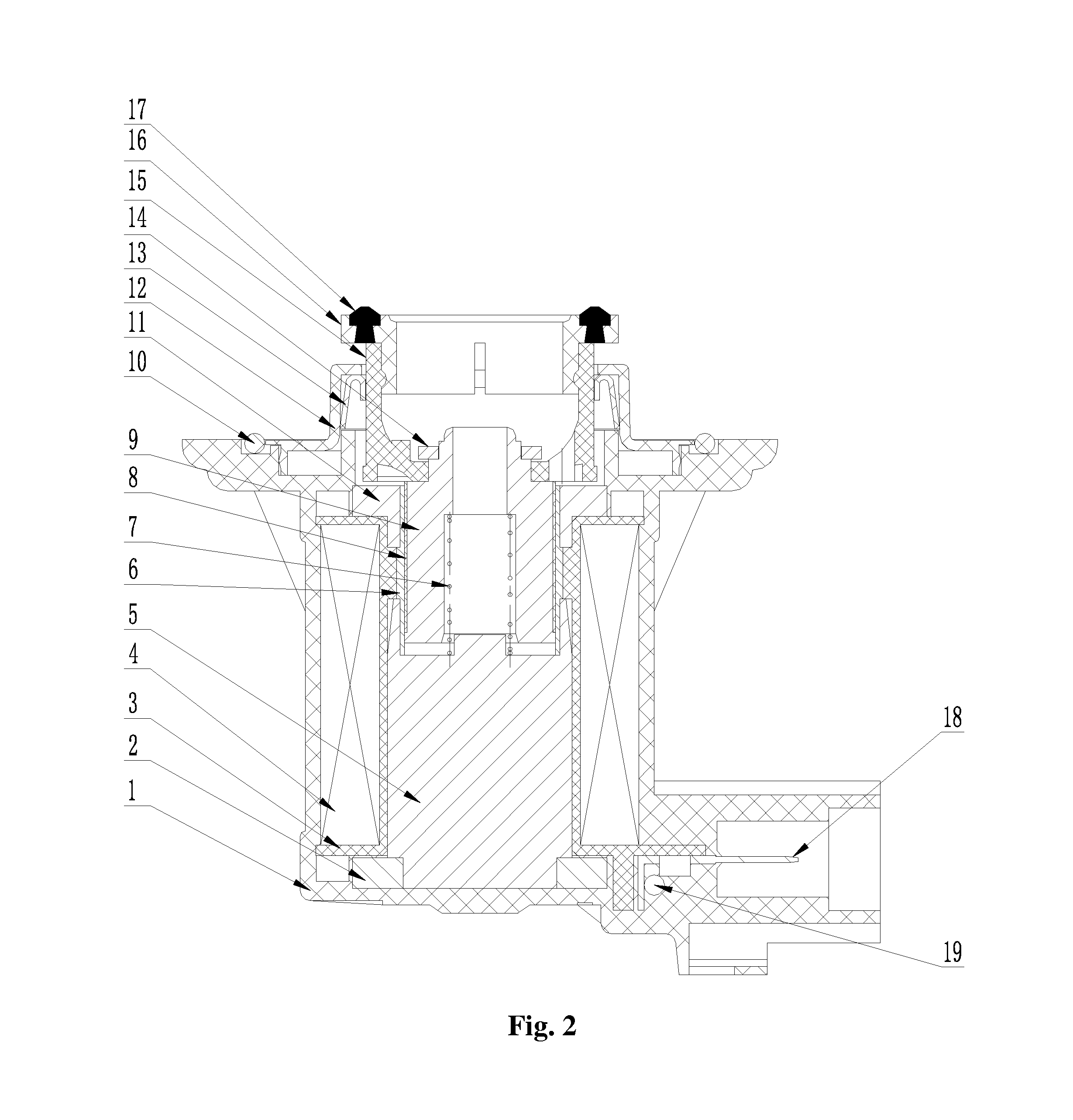
[0032]As shown in FIG. 1, a new electromagnetic relief valve for turbocharger in the embodiment comprises a high-temperature-resistant plastic valve body 1 with an electronic element resistor 19 and a connecting copper piece 18, wherein, the valve body 1 seals the electromagnetic bonnet 12 by an O-shaped seal ring 10, the bottom of the valve body 1 is provided with a static core 5, the periphery of the bottom of the static core 5 is provided with a magnetic conductive disc 2, the upper part of the magnetic conductive disc 2 is provided with a coil holder 3 and the coil holder 3 is provided with a coil winding 4 wrapped around the periphery of the static core 5.
[0033]The top of the valve body 1 is provided with a dynamic core 9 corresponding to the static core 5, a compressed spring 7 is provided between the dynam...
PUM
 Abstract
Description
Claims
Application Information
 - R&D
- Intellectual Property
- Life Sciences
- Materials
- Tech Scout
- Unparalleled Data Quality
- Higher Quality Content
- 60% Fewer Hallucinations
Browse by: Latest US Patents, China's latest patents, Technical Efficacy Thesaurus, Application Domain, Technology Topic, Popular Technical Reports.
© 2025 PatSnap. All rights reserved.Legal|Privacy policy|Modern Slavery Act Transparency Statement|Sitemap|About US| Contact US: help@patsnap.com


