Fancooled electrical machine with axial thrust compensation

Active Publication Date: 2016-07-28
NUOVO PIGNONE TECH SRL
View PDF3 Cites 15 Cited by
  • Summary
  • Abstract
  • Description
  • Claims
  • Application Information

AI Technical Summary

Benefits of technology

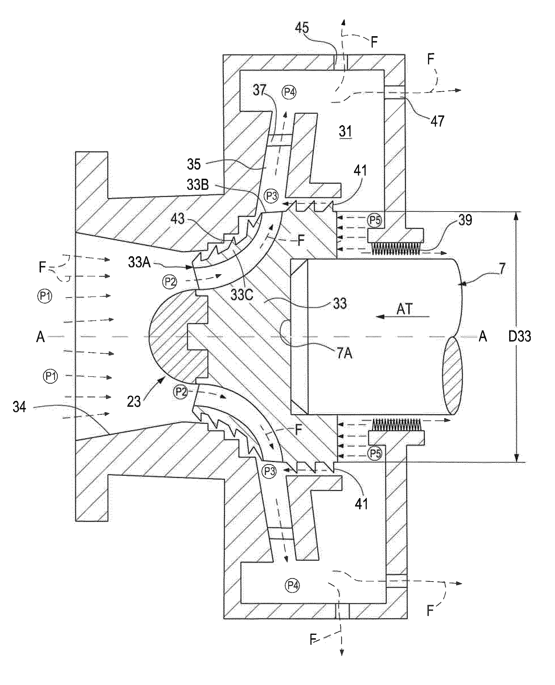
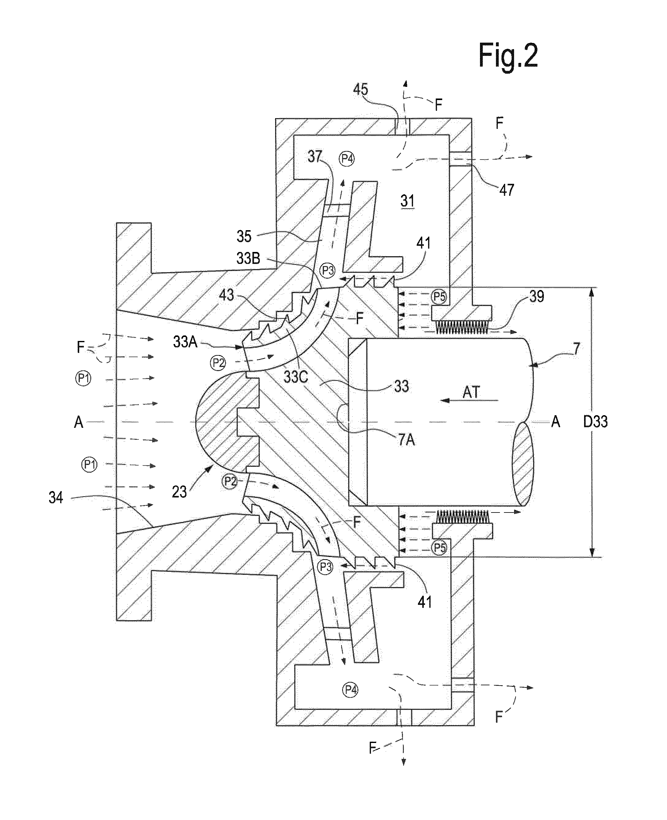
[0007]To reduce the axial thrust generated by the cooling gas pressure, a cooling-gas distribution chamber can be combined with the cooling fan. Cooling gas is delivered by a cooling fan in the cooling-gas distribution chamber at elevated pressure and therefrom distributed towards the electrical machine, e.g. through the gap between the rotor and the

Problems solved by technology

The axial force generated by the cooling flow pressure may become very significant and requires a special thrust compensating device to be used.
Even if a powerful axial thrust compensation device, such as an axial bearing, is located in the machinery connected to the electrical rotating machine to compensate for its own axial force and is capable to compensate the addi

Method used


Image

  • Fancooled electrical machine with axial thrust compensation
  • Fancooled electrical machine with axial thrust compensation
  • Fancooled electrical machine with axial thrust compensation

Examples


Embodiment Construction

[0017]The following detailed description of the exemplary embodiments refers to the accompanying drawings. The same reference numbers in different drawings identify the same or similar elements. Additionally, the drawings are not necessarily drawn to scale. Also, the following detailed description does not limit the invention. Instead, the scope of the invention is defined by the appended claims.

[0018]Reference throughout the specification to “one embodiment” or “an embodiment” or “some embodiments” means that the particular feature, structure or characteristic described in connection with an embodiment is included in at least one embodiment of the subject matter disclosed. Thus, the appearance of the phrase “in one embodiment” or “in an embodiment” or “in some embodiments” in various places throughout the specification is not necessarily referring to the same embodiment(s). Further, the particular features, structures or characteristics may be combined in any suitable manner in one...


PUM


Abstract

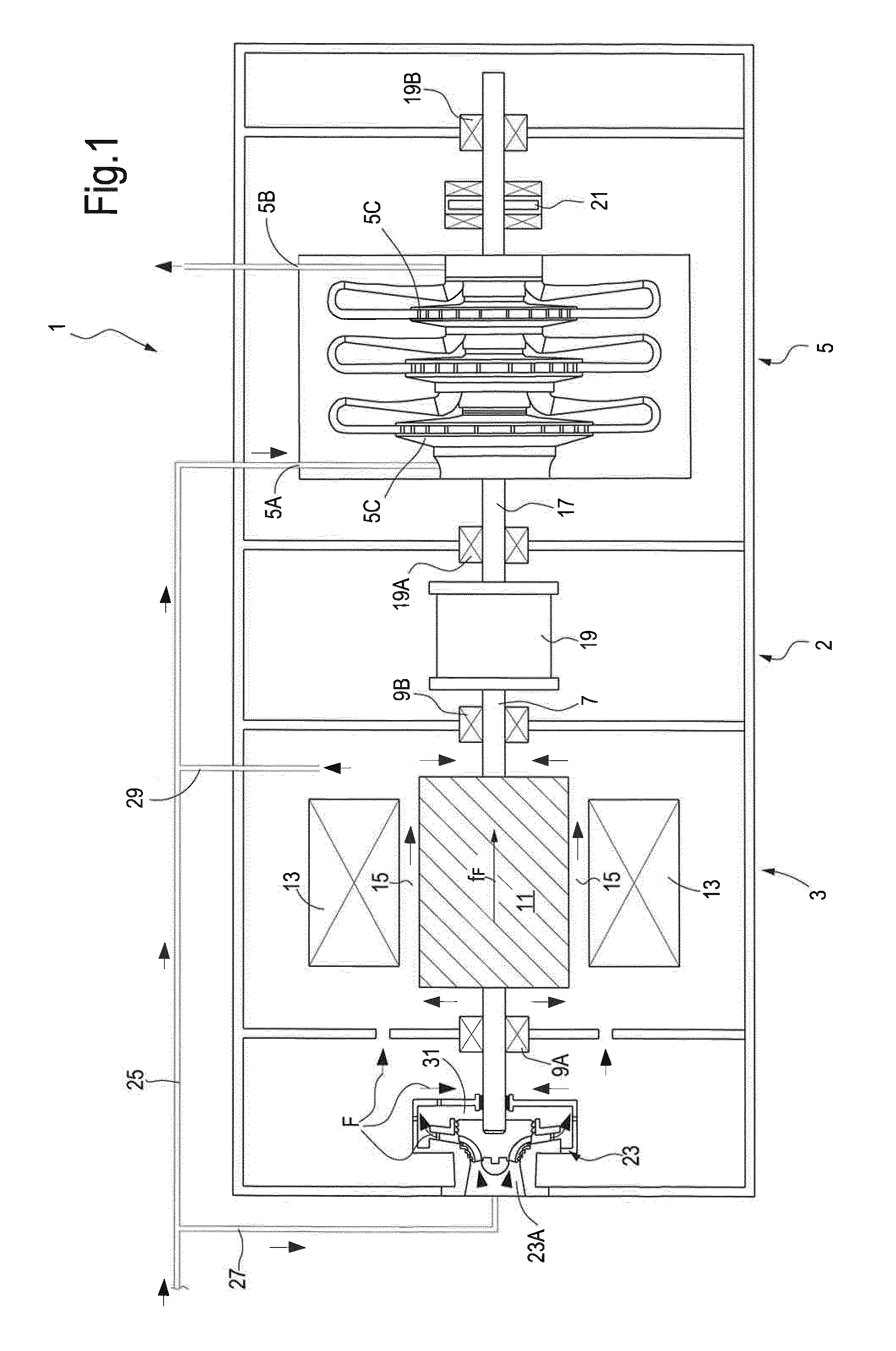
A rotating machinery equipment is disclosed, comprising a rotating electrical machine having a stator and a rotating shaft, whereon a rotor is mounted. The machinery equipment further comprises a cooling fan comprised of a rotating impeller mounted on the rotating shaft for co-rotation therewith. Cooling gas passages are provided for delivering compressed cooling gas through the stator and rotor. The cooling gas is delivered by the impeller into a cooling-gas distribution chamber. The pressure of the cooling gas in the cooling-gas distribution chamber generates an axial force balancing the axial thrust generated on the electrical machine by the cooling gas flow.

Description

TECHNICAL FIELD[0001]The present disclosure relates to rotating machines and in particular to rotating electrical machines. Some embodiments of the present disclosure relate to rotating machinery equipment including a rotating electrical machine and a turbomachine drivingly connecting thereto.BACKGROUND[0002]Electrical machines are often used as prime movers connected to a driven equipment, such as a compressor or a pump. Electrical machines are also used as generators, drivingly connected to a prime mover, such as an internal combustion engine, for example a gas turbine or a reciprocating internal combustion engine.[0003]Electrical machines are sometimes provided with a cooling fan mounted on the shaft thereof, for the generation of a flow of cooling fluid, such as typically a flow of cooling gas. In some known arrangements, electrical motors used as prime movers for turbo-compressors use the same gas processed by the turbo-compressor as cooling medium.[0004]In a high-speed electri...

Claims


Application Information

Patent Timeline
IPC IPC(8): H02K7/18F04D29/041H02K9/06
CPCH02K7/18F04D29/041H02K9/06H02K7/14H02K7/1823F04D17/122F04D25/06F04D29/5806F04D29/0516F04D29/162
Inventor OXMAN, ILIAMICHELASSI, VITTORIO
Owner NUOVO PIGNONE TECH SRL
Why Eureka
Try Eureka