Pumping system

a technology of pumping system and pumping motor, which is applied in the direction of pump control, motor parameter, cleaning using liquids, etc., can solve the problem that the replacement time cannot be estimated

Active Publication Date: 2016-08-04
SUGINO MACHINE
View PDF3 Cites 4 Cited by
  • Summary
  • Abstract
  • Description
  • Claims
  • Application Information

AI Technical Summary

Benefits of technology

[0023]According to the above-mentioned configuration, the feedforward control is made to eliminate a delay of a response of the discharge characteristic at the beginning of operation. Besides, the f

Problems solved by technology

However, the time of repla

Method used


Image

  • Pumping system
  • Pumping system
  • Pumping system

Examples


embodiment

(Configuration)

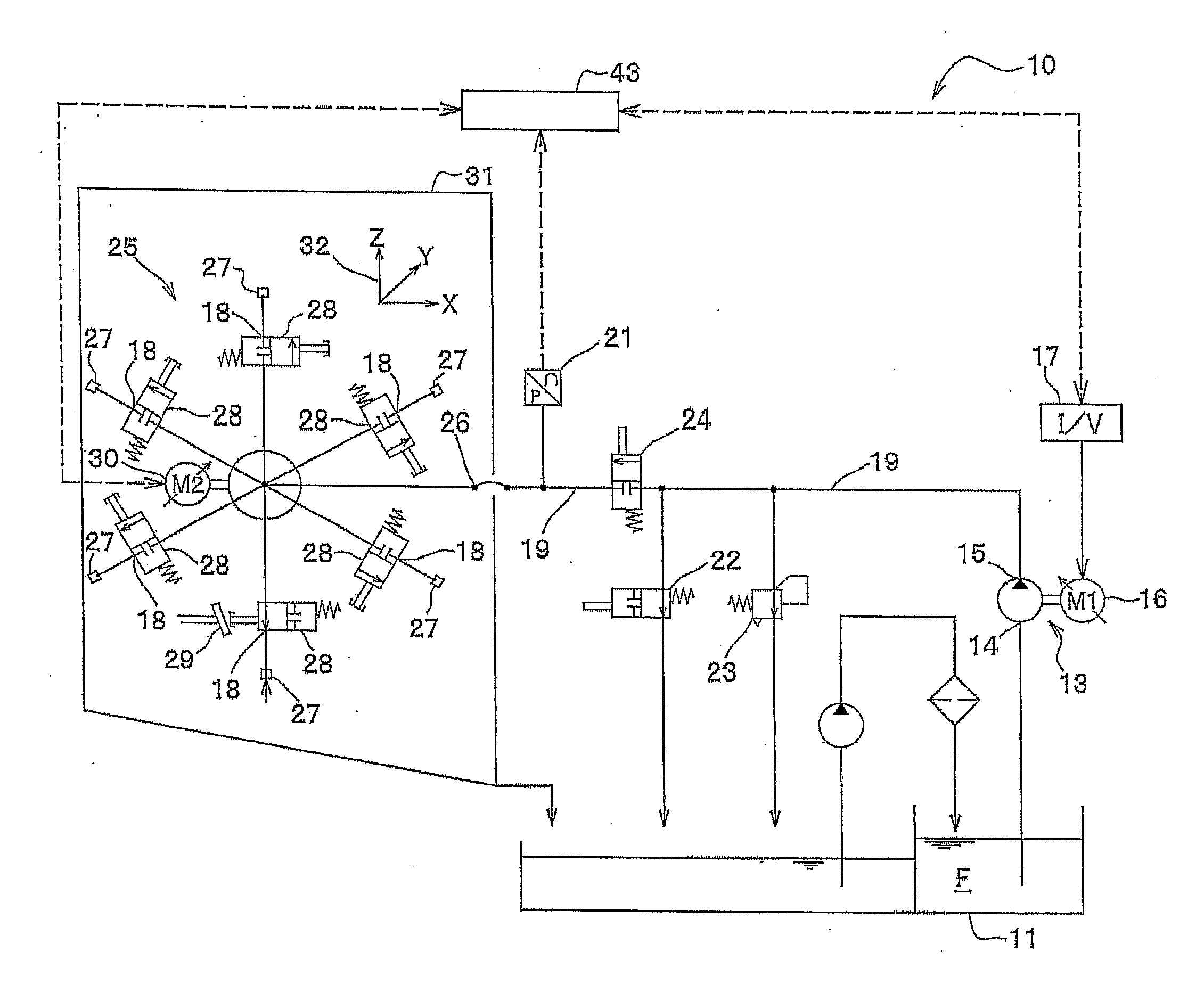
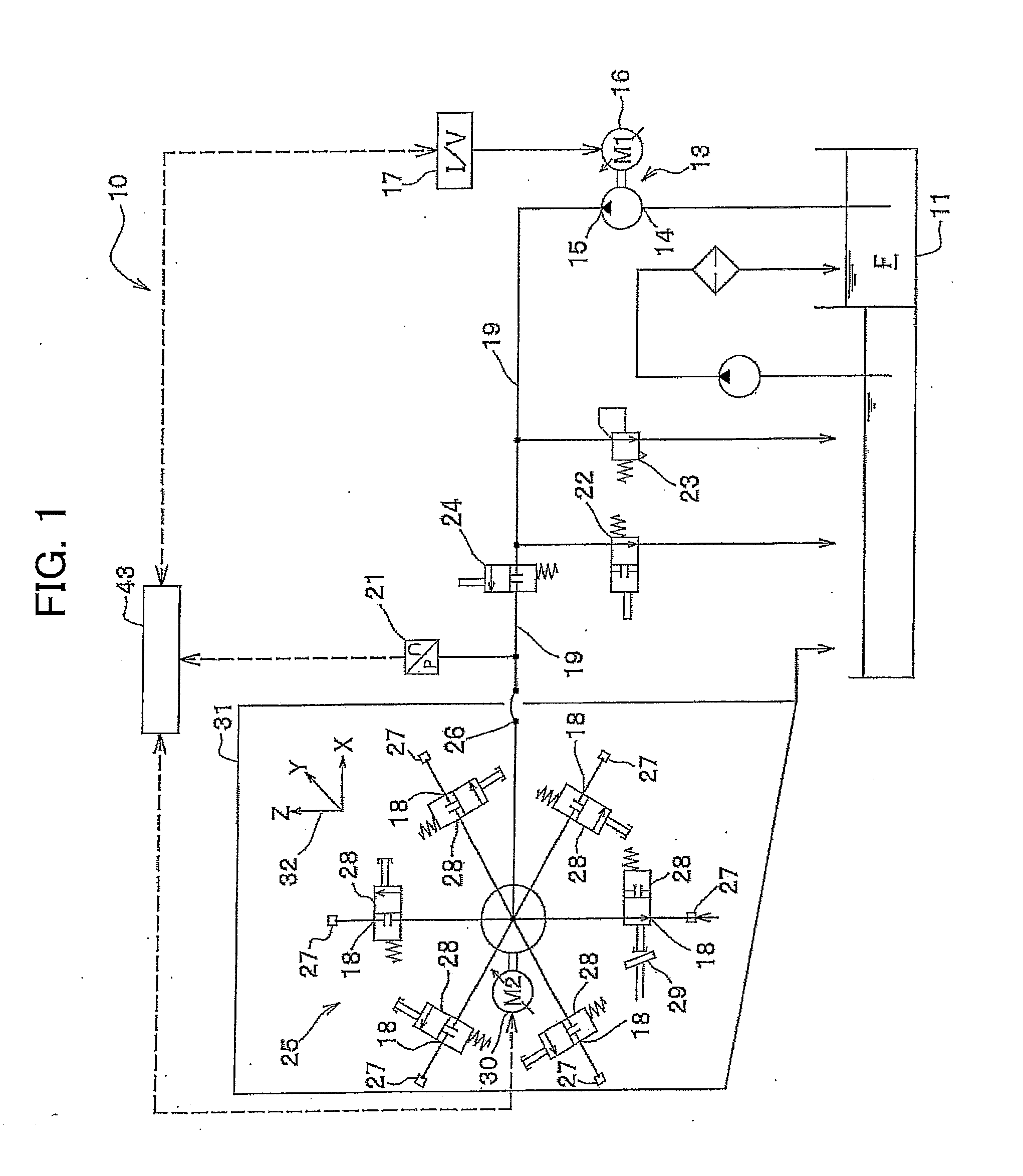
[0038]FIG. 1 shows a pumping system 10 in this embodiment of the present invention.

[0039]As shown in FIG. 1, the pumping system 10 pressurizes fluid F and jets the fluid F from a nozzle 27 selected out of a plurality of nozzles 27. The fluid F is stored in tank equipment 11. In this case, the fluid F is water or aqueous solution including a cleaner, an antiseptic, a rust preventive or an other additive. The tank equipment 11 is provided with two-vessel type filtration equipment. As the tank equipment 11 is commonly used for a washer and a cutter, its detailed description is omitted.

[0040]The pumping system 10 is provided with a positive-displacement pump. In this embodiment, the positive-displacement pump is a piston pump 13 which is provided with a plurality of plungers, which sucks the fluid F from an intake opening 14 by reciprocating the plungers and which discharges the fluid F from a discharge opening 15. Discharge pressure (a discharge characteristic) can be se...

first modification

(First Modification)

[0091]This modification is similar to the above-mentioned embodiment in that a type of a nozzle 27 to which a tool number n is allocated and a reference jet hole diameter dO of the nozzle 27 are determined, however, this modification is different from the above-mentioned embodiment in that the configuration of a control parameter when pressure can be freely varied on the way of a cleaning program is provided.

[0092]FIG. 6A shows a table 55 showing target pressure PO for the nozzle 27 of the tool number n. A column 71 shows the tool number n. A column 72 shows the target pressure PO of the nozzle 27 corresponding to the tool number n. When no nozzle 27 is allocated to the tool number n, a specific character string (for example, x) is input in the column 72. CPU 45 reads whether the nozzle 27 is allocated to the selected tool number n or not based upon contents written in the column 72, and reads the target pressure PO of the nozzle 27.

[0093]FIG. 6B shows a table 56...

second modification

(Second Modification)

[0097]In a second modification, a control parameter is acquired based upon a type of a nozzle 27, a reference jet hole diameter dO of the nozzle 27 and target pressure PO and is stored in a storage 51.

[0098]In the second modification, even if the type of the nozzle 27 and the jet hole diameter are changed for a tool number n, a controllable pumping system 10 is provided by only setting the type of the nozzle 27, the reference jet hole diameter dO of the nozzle 27 and the target pressure PO. The same reference numeral is allocated to the same configuration as that in the above-mentioned embodiment and detailed description is omitted.

[0099]FIGS. 7A, 7B, 7C show control parameters in this modification. As shown in FIG. 7A, a storage 51 stores various set values in a table 96. In the table 96, a column 82 includes a type of the nozzle 27 for the tool number n in a column 81, a column 83 includes the reference jet hole diameter dO [mm], and a column 84 includes the t...


PUM


Abstract

To keep a discharge pressure or a discharge flow rate of a pumping system that jets a fluid from a nozzle selected from a plurality of nozzles a set value every selected nozzle. A pumping system that jets the fluid from the nozzle selected from the plurality of nozzles is provided with: a piston pump as a positive-displacement pump; a permanent-magnet type synchronous motor as a rotational speed variable drive unit; a turret device as selecting arrangement; a discharge pipe; the nozzle; a controller that controls the rotational speed of the drive unit; a storage that stores control parameters and a target value of the discharge pressure corresponding to each nozzle; and a pressure sensor, wherein the controller controls the rotational speed of the drive unit by feeding back the discharge pressure using the control parameters corresponding to the selected nozzle to match the discharge pressure with the target value.

Description

BACKGROUND[0001]1. Field of the Invention[0002]The present invention relates to a pumping system, especially relates to the control of a pumping system that pressurizes fluid and jets the fluid from a nozzle selected out of a plurality of nozzles.[0003]2. Description of the Related Art[0004]There is a pumping system in which a plurality of nozzles are connected to a pump via selecting arrangement and which jets fluid discharged by the pump from the nozzle selected by the selecting arrangement. Such a pumping system is used for a cleaning device disclosed in JP-A No. H8-90365 for example. In the cleaning device disclosed in JP-A No. H8-90365, a plurality of nozzles are arranged on the upside of a turret which is selecting arrangement. Fluid discharged by the pump is jetted from one nozzle selected by the selecting arrangement.[0005]The discharge pressure of a positive-displacement pump is determined by the rotational speed (the speed of rotation per unit time) of the positive-displac...

Claims


Application Information

Patent Timeline
IPC IPC(8): F04B17/03
CPCF04B17/03B05B1/1636B05B9/0413F04B2205/05F04B49/065F04B49/08F04B2203/0209F04B23/02B08B3/02F04B49/06F04B49/10F04C14/08F04C14/28B05B15/58
Inventor KAWAMORI, YOSHITERUTAKATA, YUKINOBUSHIBATA, AKINORI
Owner SUGINO MACHINE
Why Eureka
Try Eureka