
Retrofit lamp with direct digital connection

a technology of retrofitting and digital connection, applied in the field of lighting, can solve the problems of affecting the performance of the lighting fixture, the inability of smaller venues to afford to upgrade to an expensive new product, and the drawbacks of the dimming control using a triac for each lamp. achieve the effect of high performance and economical

Inactive Publication Date: 2016-08-04
LUXAPEL LLC
View PDF1 Cites 34 Cited by
  • Summary
  • Abstract
  • Description
  • Claims
  • Application Information

AI Technical Summary

Benefits of technology

The present invention is a new type of solid-state replacement for traditional stage and studio border lighting fixtures. It allows for easy replacement of traditional bulbs while maintaining the same special effects and level of control as traditional lighting. The new system includes interconnection hardware to connect each lamp to a standard control signal so as to improve upon the behavior of the original lighting. Each lamp in the series has perfectly repeatable brightness settings, ensuring consistent lighting across the entire strip. This invention is a high-performance and cost-effective upgrade for existing border light fixtures.

Problems solved by technology

The dimming control using a triac for each lamp has drawbacks, among them audible noise, heat generation and cost.
However, it would be desirable to redeploy and reuse the original strip light fixture, avoiding the waste of material, and, in any case, some smaller venues cannot afford to upgrade to an expensive new product.
Presently there is no product in the market that can be used to directly replace border light incandescent lamps using the Edison screw base socket.

Method used


Image

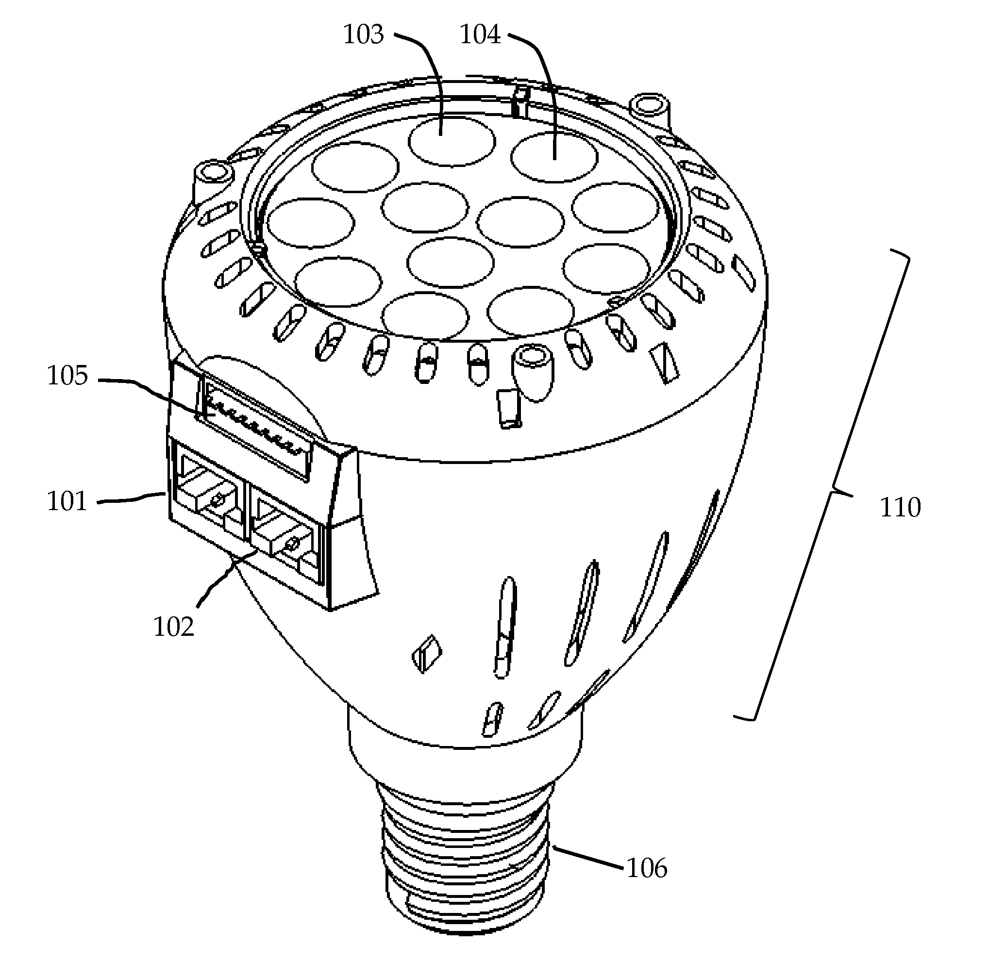
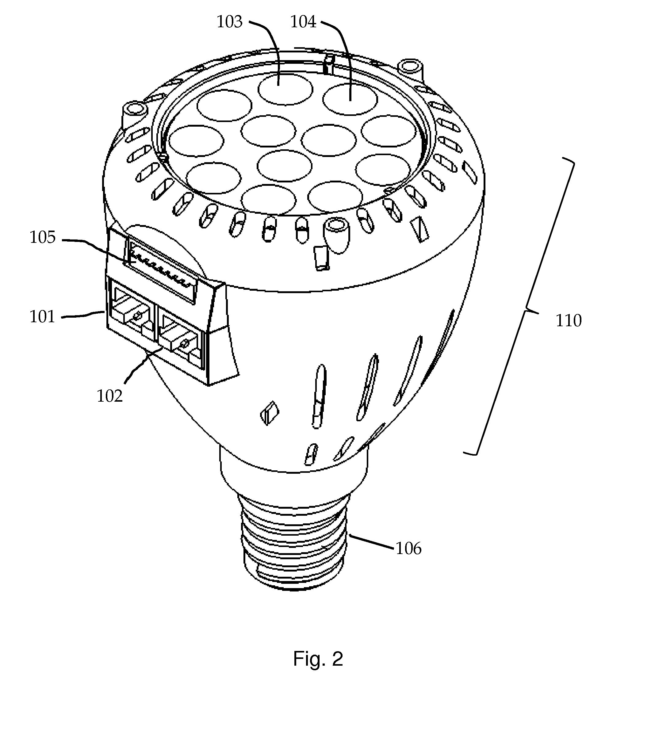
  • Retrofit lamp with direct digital connection
  • Retrofit lamp with direct digital connection
  • Retrofit lamp with direct digital connection

Examples


Embodiment Construction

[0021]The present invention relates to strip lighting or other arrays or arbitrary arrangements of illumination systems. In particular, the present invention allows an LED based light source to replace a halogen or tungsten / incandescent lamp for improved efficiency, color control, more accurate dimming values and faster response times.

[0022]The disadvantages of existing systems are well-known. Filament lamps have poor response times and low efficacy. Triac dimmers have poor reliability as they handle hundreds of watts and can burn out or otherwise fail during a performance. In contrast, solid state lighting systems are as much as ten times more power efficient and if properly designed can have a higher reliability compared to filament lamps and triac dimmers.

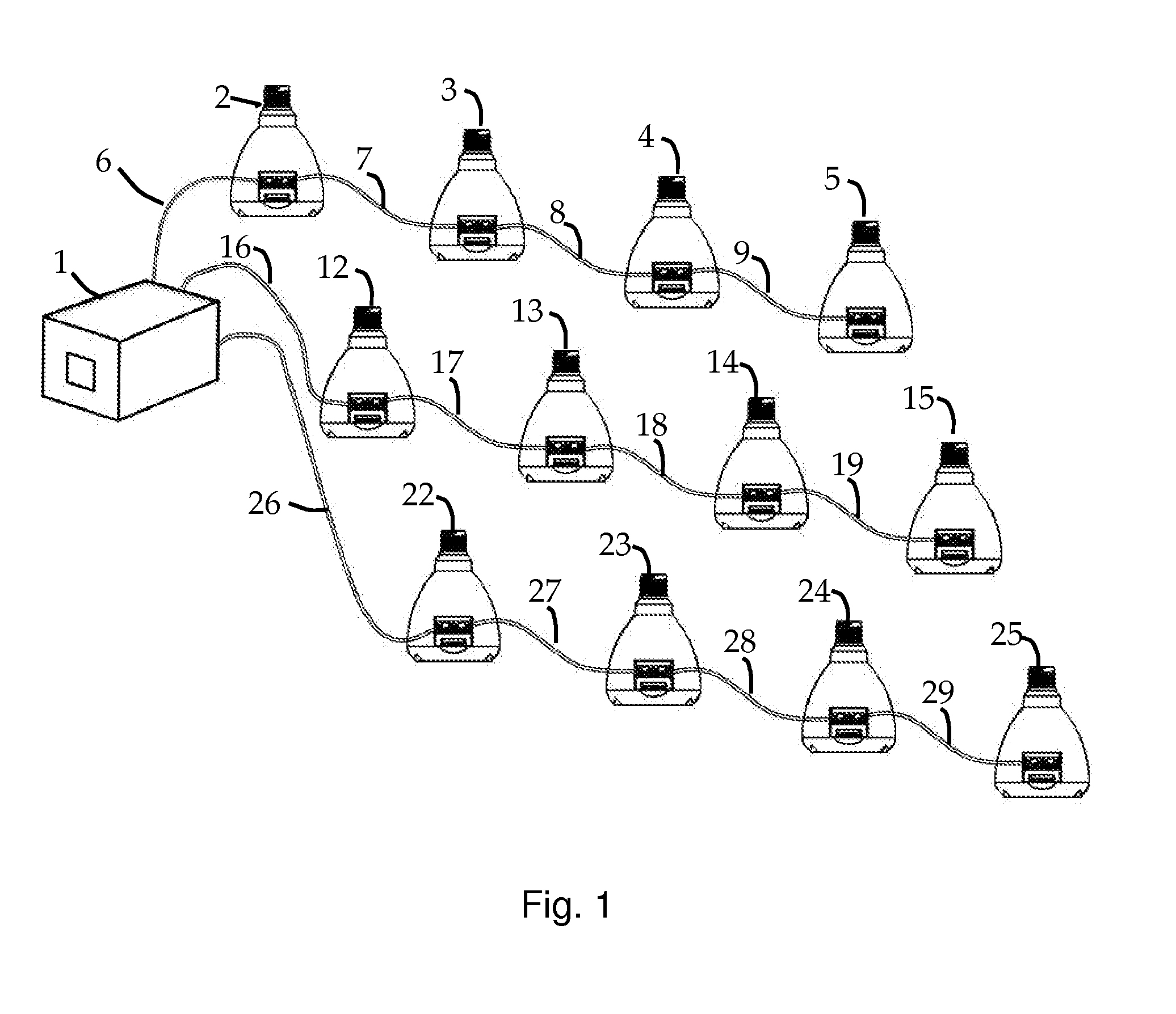
[0023]FIG. 1 shows a wiring diagram, where a controller 1 is connected to a plurality of cables 6, 7, 8 and 9 and these cables, having at least one twisted pair of conductors and according to one embodiment using Category 5 type...


PUM


Abstract

An illumination system uses a plurality of lamps with each lamp including a modular connector configured for connecting to a streaming data signal. Each lamp further includes an enumerating feature, with a second modular connector, so that a series or array of such lamps can be daisy-chained and thus connected to a control signal such as using the DMX512 standard. Each lamp is intended to retrofit a border light fixture in a stage, studio or entertainment lighting application. The enumeration of each lamp can be done by fixed assignment in the microprocessor nonvolatile memory, or by means of a dual-inline packaged switch bank (DIP switch), or by other electronic or electro-mechanical means. Such numbering is needed to allow each retrofit lamp to have a unique unit number so that it can be specifically addressed and get dimming instructions independently from other retrofit bulbs that share the same data stream.

Description

BACKGROUND OF THE INVENTION[0001]This invention relates generally to lighting and more particularly to network-controlled stage lighting.[0002]Historically a ‘border light’ has been used to create a background effect on the curtain or cyclorama of the cabaret or stage. Whether the venue is large or small, it is desirable to have a row of lights hanging overhead and pointing downward to create a mood or background or theme by selecting the right combination of colors. There might also be a need for a row of lights at the front of the stage pointing up (footlights), also used to create a dramatic mood to front-light the stage or curtain or the actors.[0003]There are thousands of venues using Borderlights made by Altman Lighting Co. Inc of Yonkers, N.Y., (and similar fixtures made by other companies), which are generally installed over the stage area with typically 48 to 80 sockets, most often populated with 150 W halogen PAR38 or 250 W R40 bulbs with each bulb having a gelatin color f...

Claims


Application Information

Patent Timeline
IPC IPC(8): H05B37/02H05B33/08H05B44/00
CPCH05B37/0254H05B33/0857H05B33/0845H05B45/20H05B47/18
Inventor CONNER, ARLIETAMMIK, OKE
Owner LUXAPEL LLC
Learn More