Methods of manufacturing and cleaning

a manufacturing and cleaning technology, applied in the direction of manufacturing tools, machines/engines, stators, etc., can solve the problems of inability to remove excess powder from internal cavities, process complexity, and limited known techniques,

Active Publication Date: 2016-08-11
ROLLS ROYCE PLC
View PDF11 Cites 18 Cited by
  • Summary
  • Abstract
  • Description
  • Claims
  • Application Information

AI Technical Summary

Benefits of technology

[0019]Preferably the impacting element is made from the same material as the component. Manufacturing the impacting element from the same material as the host component prevents cross contamination and damage due to wear. This enables the powder to be directly recycled back into the hopper of the additive manufacturing machine reducing waste and cost.
[0021]The retaining member may be, for example, a grid or bar, or series of bars. The retaining member enables the powder to fall out of the internal portion preventing damping of the motion of the impacting element, but retains good transfer of momentum from the component to the impacting element. This can decrease the total length of time required for the impacting element to clean the entire internal portion as successive impacts are not dampened by the powder from previous impacts.
[0028]Providing the impacting element and the retaining member during the additive manufacturing process makes it possible to have a highly automated cleaning process, and therefore simple to integrate the cleaning process within an overall automated manufacturing process for the component.
[0030]This process can be utilised in the manufacture of many aerospace components by EBM. Without limitation, this can include engine structures such as engine section stators, heat exchangers, ducts and housings manufactured for use in gas turbine engines. Using a disc-shaped impacting element, and containing the disc inside the internal channels and applying high amplitude vibration enables effective automated clearing of the internal channels and cavities of these components.
[0031]In most instances the excess powder must be removed from the external and internal surfaces following manufacture. The impacting disc method may enable future additive manufacture of hollow components such as fuel injector nozzles, valves, pipework etc. By altering the geometry of the impacting element to one or more ball-shaped elements or other solid shapes, the process could be amended to clear different channels or internal profiles. The retaining element could also be adjusted to suit the size and shape of the impact element and the channel aperture.
[0033]Preferably the step of forming includes forming the impacting element within the internal portion. This makes it possible to have a highly automated manufacturing process for the component and the impacting element is automatically formed from the same material as the component, with the advantages previously discussed.

Problems solved by technology

Additive manufacturing is still an emerging process in the aerospace industry and suffers from a particular disadvantage in that there are limited known techniques of removing the excess powder from internal cavities.
However, for cleaning and smoothing internal cavities and channels, the processes are more complex.
One of the factors affecting the rate of abrasion / cleaning is the surface area available to contact the media.
Certain internal channels and cavities will have a small aperture with respect to the size of the external surface area of the component in which they are formed therefore access into the channel will be limited.
As a result of the slow erosion rate, significant periods of time would be needed to clear the entire channel or cavity by this method.
Sharp or sensitive features on the external surfaces would become rounded off and damaged if this technique was applied for long periods of time.
The current blasting and chiselling technique is also quite slow.
Also, some powder remains on the walls of the channel and there is difficulty in clearing bends as a direct line of sight is required for the tool.

Method used


Image

  • Methods of manufacturing and cleaning
  • Methods of manufacturing and cleaning
  • Methods of manufacturing and cleaning

Examples


first embodiment

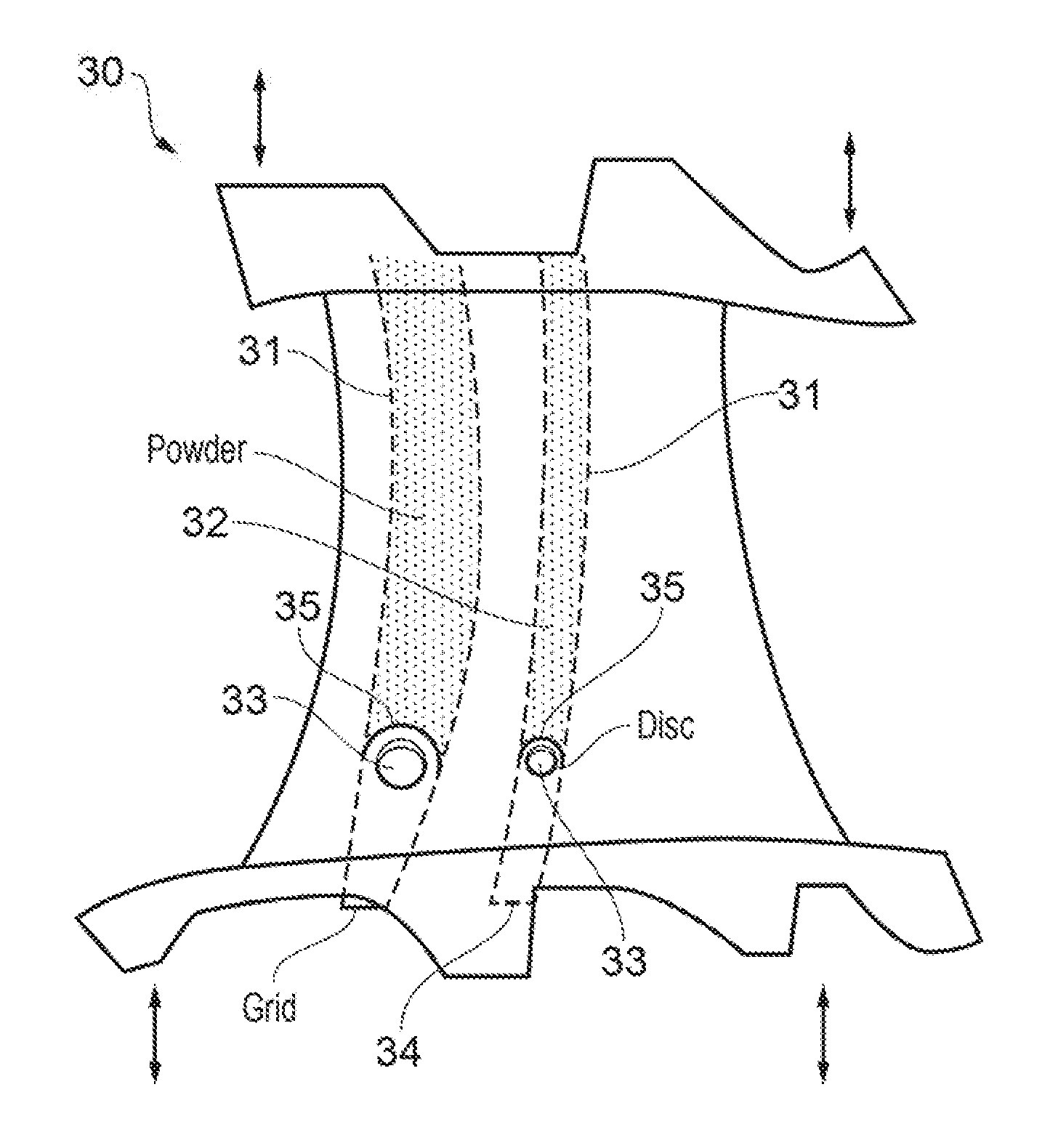
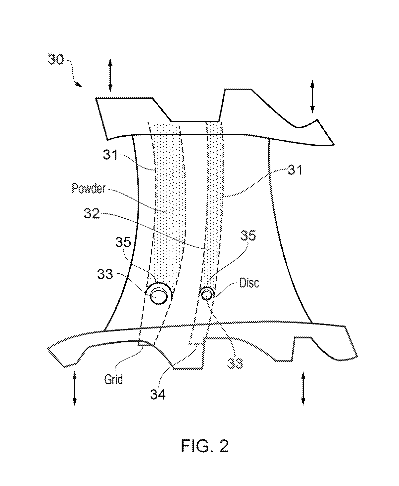
[0050]In a method according to the present invention, the disc(s) 33 are inserted into the channels 31 and contained therein using containment grids 34 which are fixed on the inner / outer annulus faces of the component 30 so as to cover the exits from the channels 31. This method is illustrated schematically in FIG. 3.

[0051]To insert the disc into the channel 31, a depth equal to that of the diameter of the disc must first be cleared out, for example using traditional air blasting techniques (or chiselling with the titanium rod). The disc 33 can then be inserted into the channel 31 and contained using a grid / bar 34 that fastens onto the component 30 at one end of the channel 31. This grid / bar contains the disc 33 within the channel 31 allowing loosened powder to fall out of the channel by gravity. The powder 32 is loosened by vibrating the component 30, causing the disc 33 to repeatedly impact on the powder as described in more detail below. This process requires a degree of manual s...

second embodiment

[0052]In a method according to the present invention, the disc(s) 33 are provided to and retained in the channels 31 by a containment extension 35 which is attached onto the end of the channel 31 when the component 30 is placed on a vibrating shaker or other vibration source. This method is illustrated in FIG. 4.

[0053]The method using the containment extension 35 is an adaptation of the method of the first embodiment discussed above. This method has the benefit that the initial depth of powder 32 does not need to be removed from the channel 31, which makes the clearing process more automated and can provide for faster turnaround times. However, some manual set-up is still required. Further, by adding the extension bracket, higher frequency amplitudes may be required to enable the disc to travel the additional distance.

third embodiment

[0054]In a method according to the present invention, the discs 33 (or alternative impacting media) and the containment feature are sintered into the component during manufacturing. This method provides for a more automated approach to the cleaning.

[0055]To improve the automation of the clearing process, in the method according to the third embodiment, as illustrated in FIG. 5, the impacting media (e.g. discs 33, balls, pellets etc.) and the containment feature 36 are sintered in during the manufacture of the hollow component 30. The impacting media 33 is loosened prior to, or as part of, starting the shaking process to enable the media to gather momentum within the channel 31 and start the clearing process. For example a dropout 37 may be provided in the containment feature 36 which is formed of looser powder (e.g. similar to the powder formed in the cavity or channel 31). This dropout 37 may be shaken free at the start of the cleaning process. Alternatively, if sufficient energy i...


PUM

PropertyMeasurementUnit
rotational symmetryaaaaaaaaaa
surface areaaaaaaaaaaa
sizeaaaaaaaaaa

Abstract

Methods of cleaning internal portions of additively manufactured components are provided, together with an apparatus for carrying out the cleaning. The methods use an impacting element which is contained within the internal portion and the component is vibrated to clean material from the component and leave one or more hollow portions. Various embodiments for retaining the impacting element are set out, which preferably use a grid which allows loosened powder to fall out of the component and, optionally, be recycled for use in further manufacturing processes. The methods are described in relation to components for gas turbine engines but have wider application in relation to any additively manufactured component in which it is desired to have a hollow internal portion.

Description

FIELD OF THE INVENTION[0001]The present invention relates to methods of cleaning internal portions of additively manufactured components and methods of manufacturing such components. It is particularly, but not exclusively, concerned with methods in which an impacting medium is contained within the internal portions and the component vibrated to clean material from the component and leave one or more hollow portions.BACKGROUND OF THE INVENTION[0002]Additive manufacturing is still an emerging process in the aerospace industry and suffers from a particular disadvantage in that there are limited known techniques of removing the excess powder from internal cavities.[0003]In other applications vibration finishing or peening are used. Both of these concepts use surrounding media to impact the surfaces of components to smooth or clean the surfaces. These concepts are usually used on external surfaces for solid components, for example on turbine blades following investment casting manufactu...

Claims


Application Information

Patent Timeline
Patent Type & Authority Applications(United States)
IPC IPC(8): B08B7/02F01D25/24B22F3/105B23K15/00B23K26/342F01D9/02F01D25/08
CPCB29C67/0096B33Y10/00F05D2230/10F05D2220/32F01D25/24F01D25/08F01D9/02B23K15/0086B22F3/1055B08B7/02B23K26/342B33Y40/00F05D2230/22B29C64/35B29C64/357Y02P10/25B22F10/25B22F10/68B22F10/28B22F10/73B33Y40/20
Inventor WILLIAMSON, PETERHAWLEY, RICHARDNEELY, DAVID
Owner ROLLS ROYCE PLC
Why Eureka
Try Eureka