Internal combustion engine

Active Publication Date: 2016-08-11
BOARD OF TRUSTEES OPERATING MICHIGAN STATE UNIV
View PDF13 Cites 34 Cited by
  • Summary
  • Abstract
  • Description
  • Claims
  • Application Information

AI Technical Summary

Benefits of technology

[0005]The internal combustion engine of the present invention is advantageous over traditional devices. For example, the present device and method precisely control a pre-chamber prior to the end of compression, fuel and air mixture while also precisely controlling and causing the pre-chamber pressure to be the same as or greater than that of the main combustion chamber during at least one operating condition. This reduces if not entirely prevents backfeeding from the main chamber to the pre-chamber. The present engine also provides significant pre-chamber purging with fresh air alone, during an intake stroke of the main driving piston and during the compression process depending on operating conditions. This pre-chamber purge also lowers the overall cycle average pre-chamber wall temperature, thereby reducing heat transfer loss

Problems solved by technology

It is noteworthy, however, that the Kojic pre-chamber piston is disadvantageously intended to solely compress the pre-chamber mixture to cause auto-ignition without a spark plug or the like.
Differently, the Attard device only has fuel injected into the pre-chamber and the fuel-air mixture from the combustion chamber backfeeds into the pre-chamber thereby disadvantageously causing an uncontrolled fuel and air ratio within the pr

Method used


Image

  • Internal combustion engine
  • Internal combustion engine
  • Internal combustion engine

Examples


Embodiment Construction

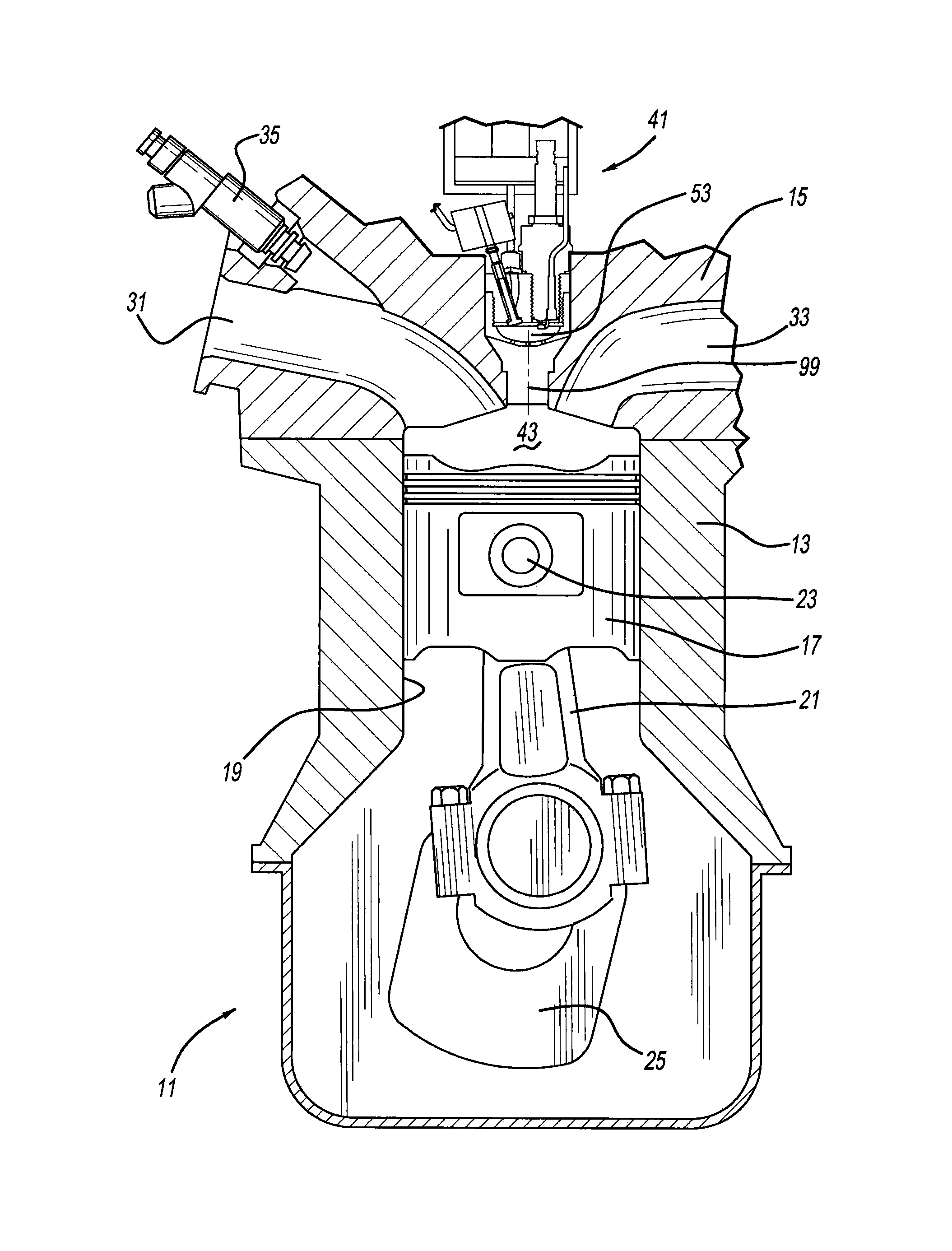
[0021]Referring to FIG. 1, an internal combustion engine 11 of an automotive vehicle includes an engine block 13 and a cylinder head 15 mounted thereto. A main driving piston 17 operably advances and retracts within a cylinder cavity 19 in order to drive a connecting rod 21 spanning between a pin 23 of piston 17 and a crank shaft 25. Furthermore, cylinder head 15 includes an intake manifold 31, an exhaust manifold 33, a direct (not shown) or port fuel injector 35 and a first embodiment turbulent jet ignition system 41. A main combustion chamber 43 is located above main piston 17 partially within cylinder cavity 19 and cylinder head 15, directly below turbulent jet ignition system 41.

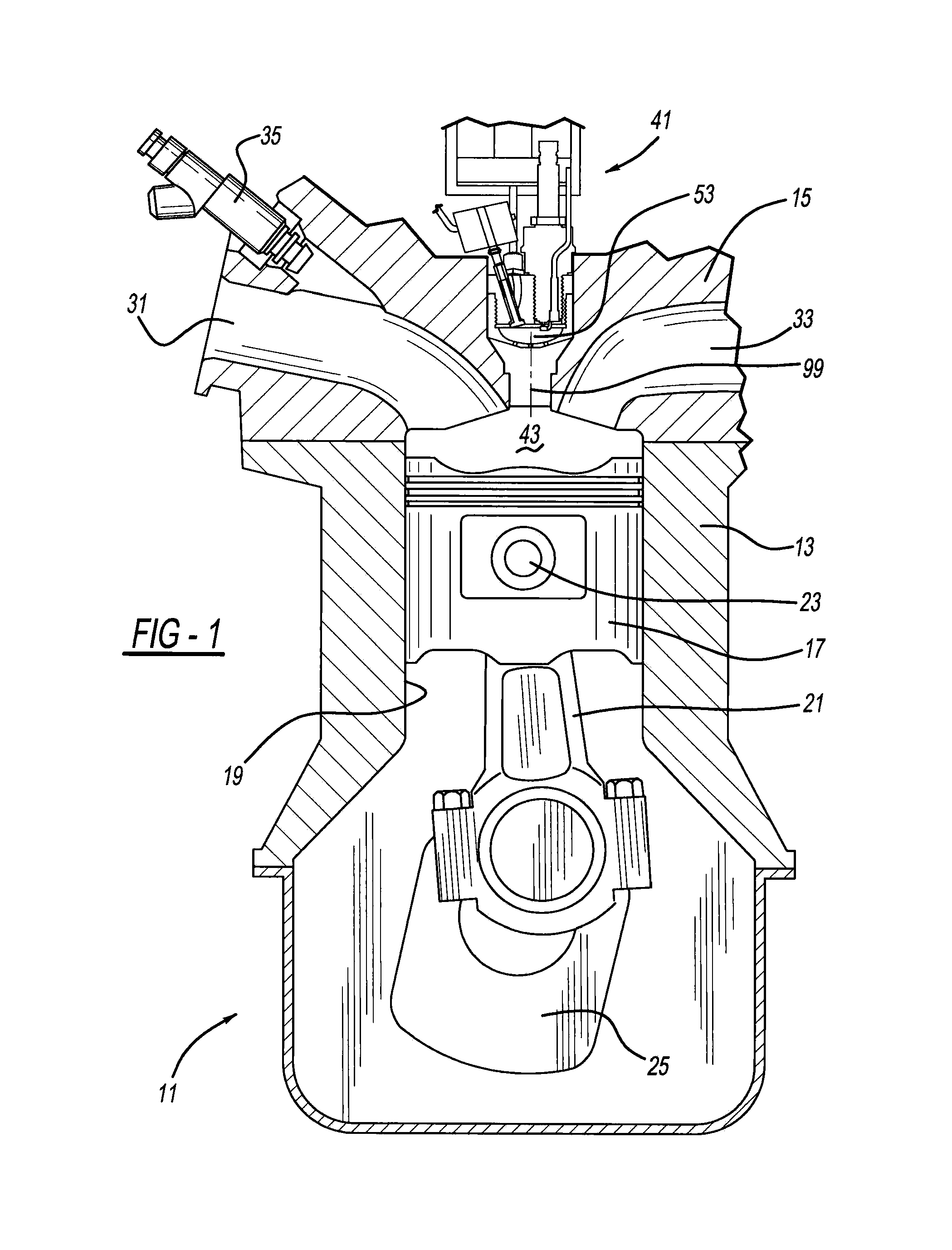
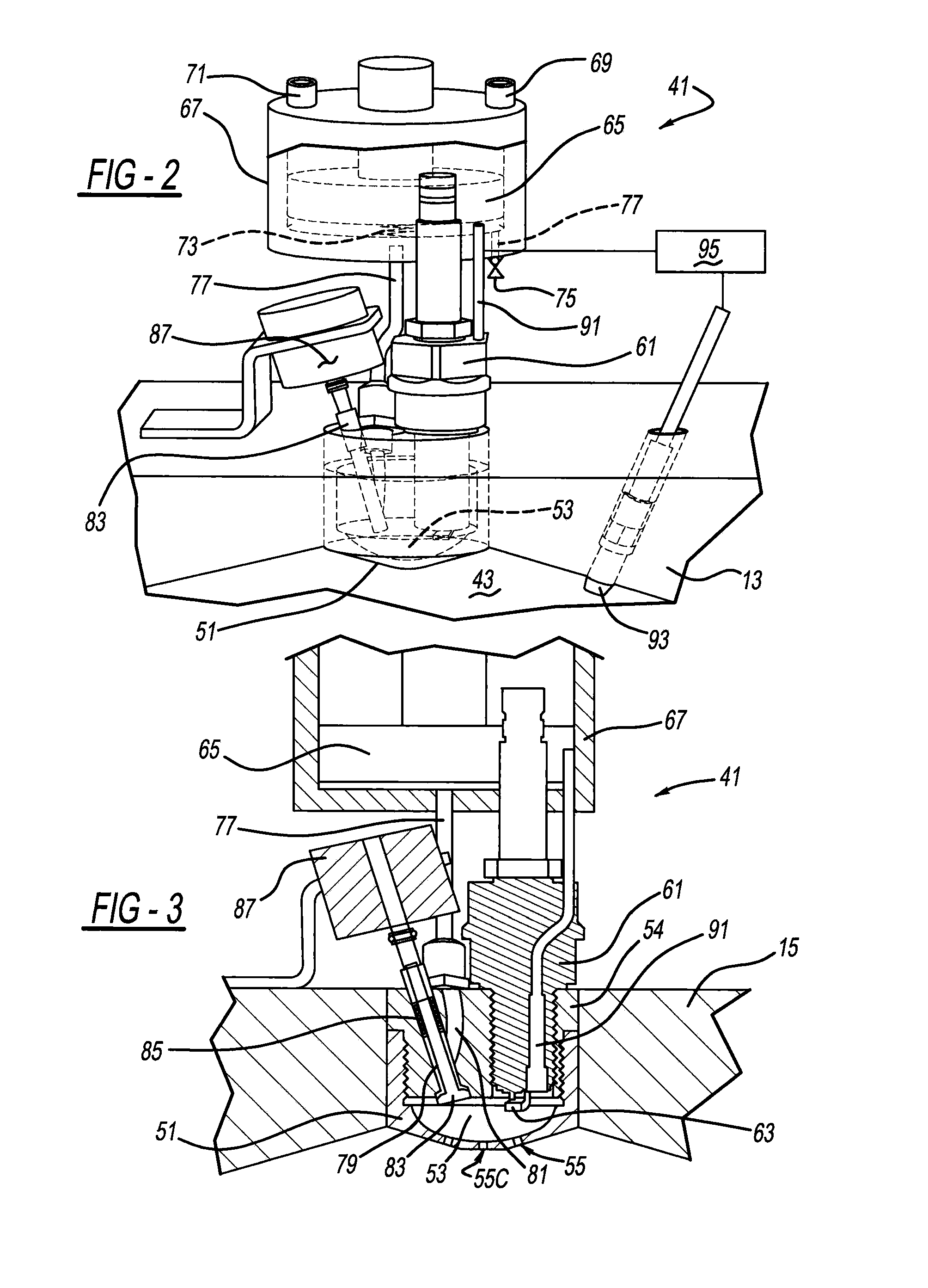
[0022]Referring now to FIGS. 2 and 3, the first embodiment turbulent jet ignition system 41 includes a cup-shaped housing 51 which internally defines the pre-chamber 53 therein. Housing 51 is secured to cylinder head 15 and a cap 54 is in threaded engagement with an upper section of the housing. At least...


PUM


Abstract

An internal combustion engine includes a pre-chamber. In another aspect, pressure within a pre-chamber is equal to or greater than pressure within a main combustion chamber at least prior to ignition in the main combustion chamber. A further aspect provides a supplemental piston creating pressure and supplying a fuel-air mixture into a pre-chamber, and a spark or glow plug has an end located within the pre-chamber for ignition of the mixture therein. In yet another aspect, internal combustion engine control software automatically controls pressure within a turbulent jet ignition pre-chamber, controls a valve-actuator to admit a fuel-air charge into the pre-chamber, and causes an ignitor to initiate combustion in the pressurized pre-chamber. This also permits the rate of combustion to be controlled in the primary chamber regardless of the air-fuel ratio or the diluent fraction in the main chamber. Another aspect employs a pre-chamber purge pump with separate air and fuel injection. Moreover, an additional aspect separately supplies unmixed air and fuel into a turbulent jet ignition pre-chamber through a dual-mode, single injector unit.

Description

CROSS-REFERENCE TO RELATED APPLICATIONS[0001]This application is a continuation-in-part of U.S. patent application Ser. No. 14 / 086,168, filed on Nov. 21, 2013, which claims the benefit of U.S. Provisional Application Ser. No. 61 / 730,184, filed on Nov. 27, 2012, both of which are incorporated by reference herein.BACKGROUND AND SUMMARY[0002]The present application generally pertains to internal combustion engines and more particularly to an internal combustion engine including pre-chamber ignition.[0003]Various pre-chamber ignition systems have been experimented with in an effort to reduce engine emissions while simultaneously increasing fuel efficiency. Such traditional systems are discussed in E. Toulson, H. Schock and W. Attard, “A Review of Pre-Chamber Initiated Jet Ignition Combustion Systems,” SAE Technical Paper, 2010-01-2263 (Oct. 25, 2010). Further examples of conventional pre-chamber engines are U.S. Patent Publication No. 2012 / 0103302 entitled “Turbulent Jet Ignition Pre-Ch...

Claims


Application Information

Patent Timeline
IPC IPC(8): F02B19/12F02P23/00F02F1/42F02B35/00F02B19/10
CPCF02B19/12F02B35/00Y02T10/125F02F1/4285F02P23/00F02B19/1052F02B19/06F02B19/1023F02B19/1028F02B19/1042Y02T10/12
Inventor SCHOCK, HAROLDZHU, GUOMINGTOULSON, ELISASTUECKEN, THOMAS RICHARD
Owner BOARD OF TRUSTEES OPERATING MICHIGAN STATE UNIV
Why Eureka
Try Eureka