
Plate fin heat exchangers and methods for manufacturing same

a heat exchanger and plate fin technology, applied in the field of heat exchangers, can solve the problems of affecting the size of the heat exchanger, prone to fouling, degrading the cooling efficiency, etc., and achieve the effects of high efficiency, low cost and high thermal conductivity

Inactive Publication Date: 2016-08-18
ENERGYOR TECH
View PDF6 Cites 8 Cited by
  • Summary
  • Abstract
  • Description
  • Claims
  • Application Information

AI Technical Summary

Benefits of technology

The patent describes a method for making heat exchangers that are lightweight and efficient, and can be used with corrosive cooling fluids like deionized water. The method involves using specific materials like flexible graphite and stainless steel film for the liquid cooling loop, and very high thermal conductivity materials like aluminum or carbon foam for the cooling fins. In one example, the aluminum fins are coated with an electrically non-conductive coating to prevent corrosion. The technical effect of this method is the production of lightweight, high efficiency heat exchangers that can withstand the use of corrosive cooling fluids.

Problems solved by technology

One major disadvantage of plate fin heat exchangers is that they are prone to fouling due to their small flow channels, and this is especially the case for aluminum alloy heat exchangers due to material compatibility issues with the cooling fluid selected.
First, it eliminates the possibility of mineral deposits within the heat exchanger that would block cooling flow and therefore degrade cooling efficiency.
This parameter not only affects the heat exchanger's size, but also the coolant flow rate necessary to reject a specific amount of heat and therefore the size, capacity and power of the coolant pump required.
Stainless steel or nickel alloy plate fin heat exchangers can be implemented where corrosive cooling fluids (i.e. deionized water) are required, but these constructions are much heavier that aluminum alloy designs and are not favorable for weight critical applications such as aerospace.
Titanium plate fin heat exchangers can also be used when corrosive cooling fluids are present, and they offer some weight advantage over stainless steel and nickel alloy constructions (30-50% less weight), but they are very expensive and still do not offer the same level of thermal performance when compared to aluminum alloys.
Although this patent addresses the problem of using a cooling fluid such as deionized water in an aluminum alloy heat exchanger, it has a number of significant drawbacks when considering plate fin heat exchangers specifically.
Because a plate fin heat exchanger design incorporates micro-channels for the coolant flow, a Teflon coating would not be practical since it would be very difficult to coat such small channel features without the risk of blockage.
Further, the thermal conductivity of Teflon itself is very low (0.25 W / m_K) when compared to a typical aluminum alloy used for heat exchangers (202 W / m_K), and it would therefore act as a thermal insulator even if the Teflon coating was thin, thereby reducing the overall thermal efficiency of the heat exchanger.
Further, it is questionable whether the surface treatment applied would be practical and effective for the internal cooling loop of the heat exchanger since it would be applied as a post processing step after the heat exchanger is constructed, bringing into question whether the entire internal surface within the plate fin heat exchanger would be covered, thereby leaving areas of exposed aluminum which would oxidize.
Similarly, although this patent addresses the problem of aluminum oxidation within the liquid cooling loop of a plate fin heat exchanger, it does not specifically address the extremely corrosive nature of deionized water.
For example, the very lack of ions makes this coolant unusually corrosive and it is sometimes referred to as the “universal solvent,” making it one of the most aggressive solvents known.
With that in mind, aluminum coatings that may be acceptable for other “corrosive” cooling fluids will likely not be practical for use with deionized water.

Method used


Image

  • Plate fin heat exchangers and methods for manufacturing same
  • Plate fin heat exchangers and methods for manufacturing same
  • Plate fin heat exchangers and methods for manufacturing same

Examples


Embodiment Construction

Definitions

[0118]Unless otherwise specified, the following definitions apply:

[0119]The singular forms “a”, “an” and “the” include corresponding plural references unless the context clearly dictates otherwise.

[0120]As used herein, the term “comprising” is intended to mean that the list of elements following the word “comprising” are required or mandatory but that other elements are optional and may or may not be present.

[0121]As used herein, the term “consisting of” is intended to mean including and limited to whatever follows the phrase “consisting of”. Thus, the phrase “consisting of” indicates that the listed elements are required or mandatory and that no other elements may be present.

[0122]As used herein, the term “coolant flow field plate” or “fluid flow field plate” is intended to mean a plate that is made from a suitable thermally conductive material. The material is typically substantially fluid impermeable, that is, it is impermeable to the fluids typically found in heat exc...


PUM


Abstract

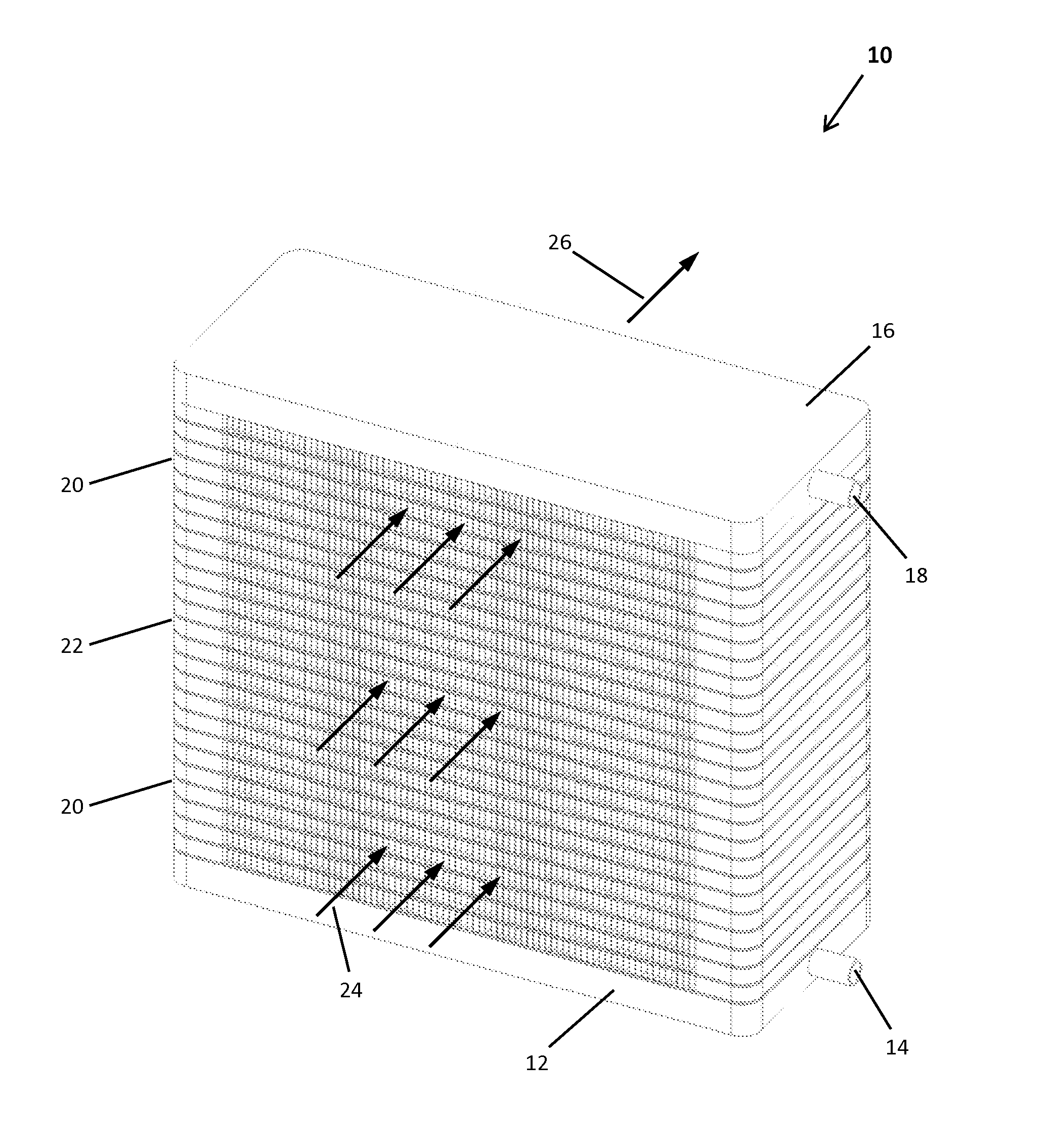
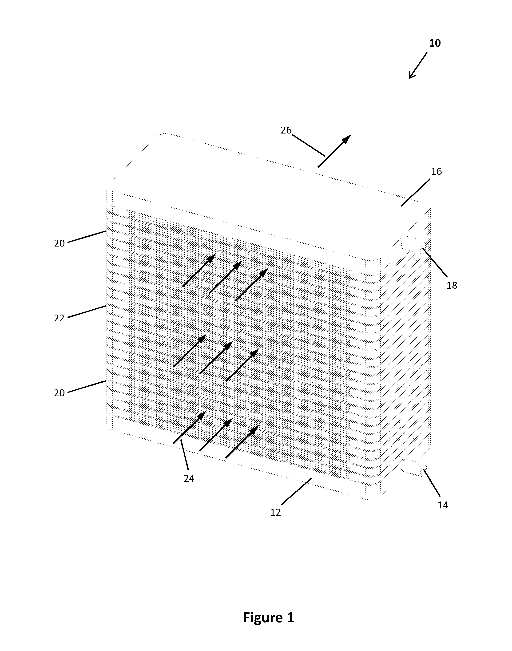
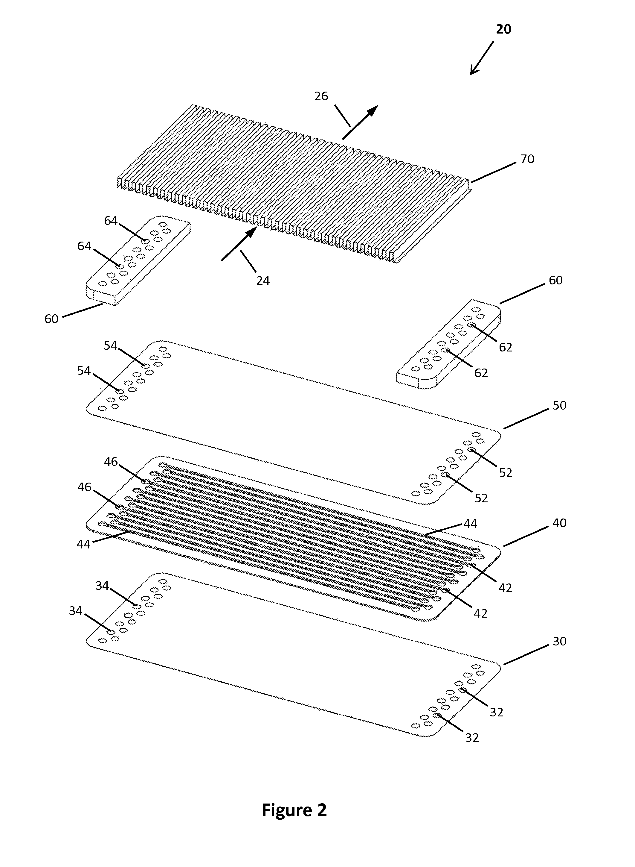
Disclosed herein is a plate fin heat exchanger subassembly. The subassembly includes three plates in intimate contact with each other. The first plate is sandwiched between the second and third plates. Each of the plates has a first at least one fluid opening and a second at least one fluid opening located at the ends of each plate. The first plate has at least one elongate fluid channel extending between the first and second fluid openings. One fluid passageway for a first heat exchanger fluid extends through the first and second fluid openings in each plate and along the elongate channel in the first plate. At least one fin has two thermal transfer surfaces. The first thermal transfer surface is in intimate contact with the second plate. The other fluid passageways for a second heat exchanger fluid are located on each side of the fin.

Description

TECHNICAL FIELD[0001]The present generally concerns heat exchangers and more particularly to a method of fabricating lightweight plate fin heat exchangers for use with corrosive cooling fluids such as deionized water.BACKGROUND[0002]Plate fin heat exchangers are generally well known in the prior art, where the heat exchanger design uses plates and finned chambers to transfer heat between fluids. The design is effectively known for its efficient construction and relatively high ratio of heat transfer surface area to volume.[0003]The plate fin heat exchanger is widely used in many industries, including aerospace and automotive applications because of its compact size and lightweight properties, and also in cryogenic systems where heat transfer between fluids with small temperature differences is possible.[0004]A plate fin heat exchanger is generally made of layers of corrugated sheets separated by flat metal plates to create a series of finned chambers. Separate hot and cold fluid str...

Claims


Application Information

Patent Timeline
Patent Type & Authority Applications(United States)
IPC IPC(8): F28D9/00
CPCF28D9/0093F28D1/0375F28D1/0383F28D2021/0043F28F3/025F28F13/003F28F21/02
Inventor JONES, THOMAS DAVIDBITTON, MICHEL MEYERSCHUHMACHER, GERRY
Owner ENERGYOR TECH
Learn More