
Charging structure

a charging structure and charging technology, applied in electric vehicles, electric power, transportation and packaging, etc., can solve the problems of reducing the life of the battery, affecting the charging effect, and causing the oscillation effect, so as to prevent the oscillation

Active Publication Date: 2016-08-18
WINBOND ELECTRONICS CORP
View PDF6 Cites 2 Cited by
  • Summary
  • Abstract
  • Description
  • Claims
  • Application Information

AI Technical Summary

Benefits of technology

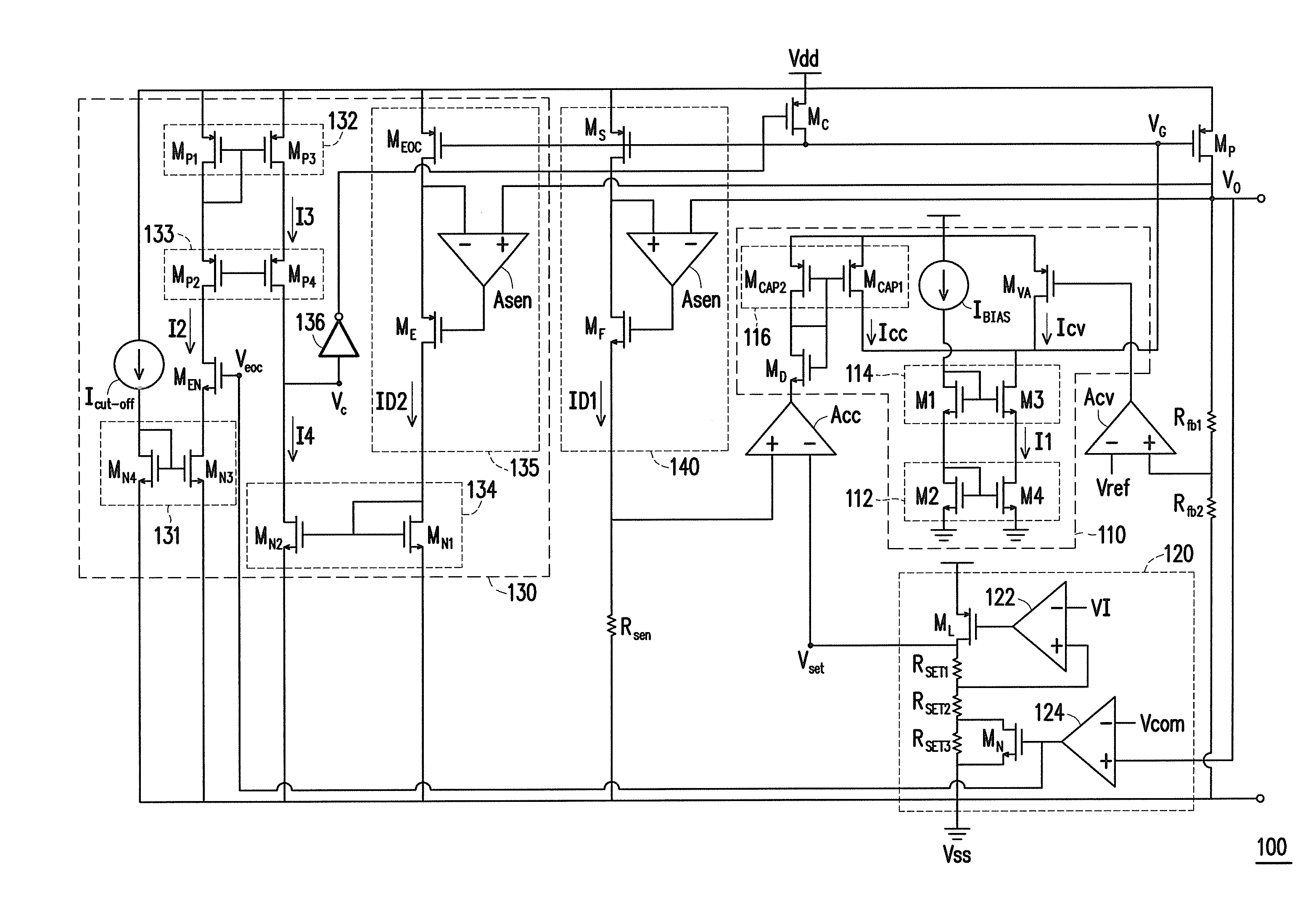
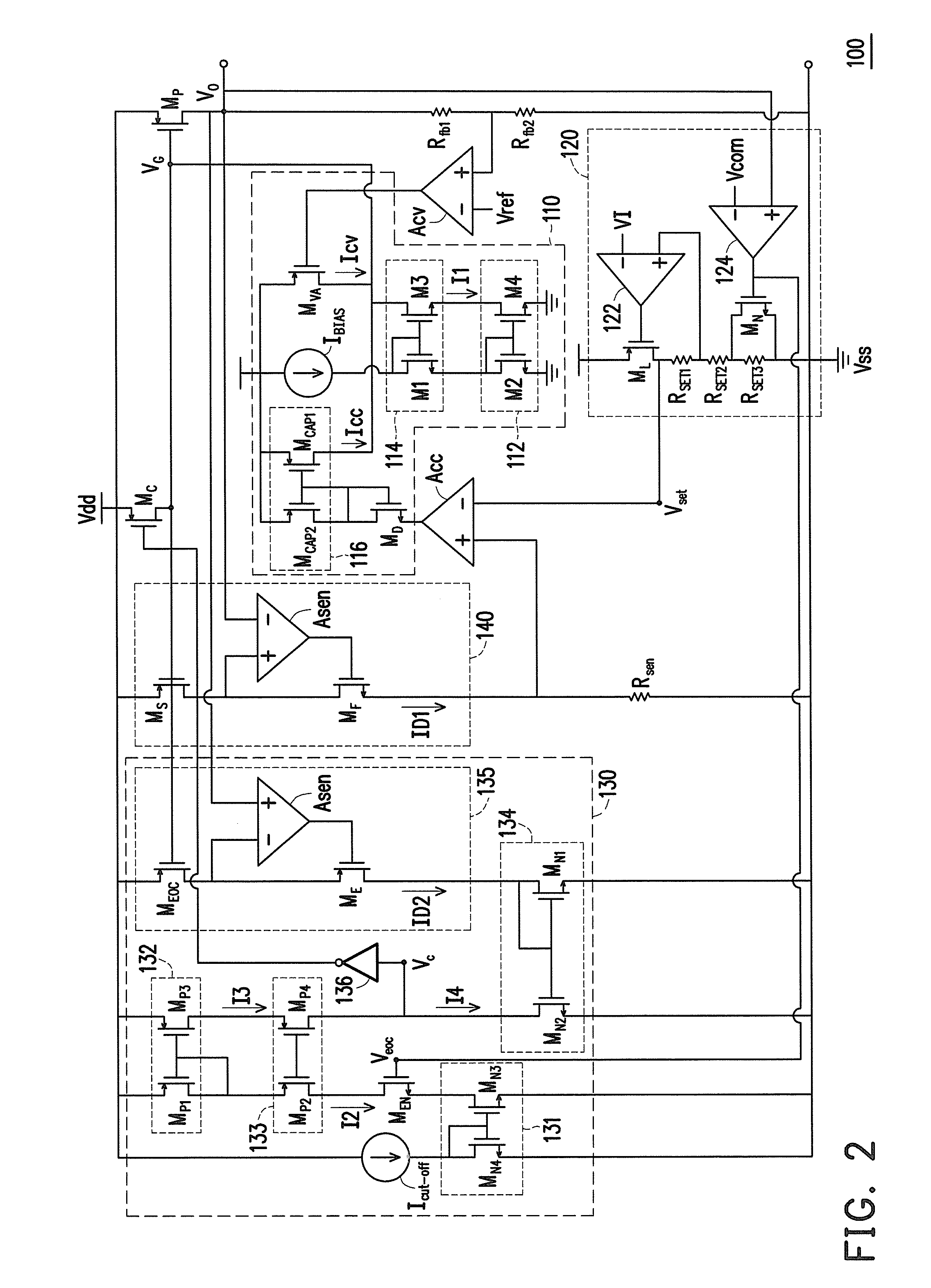
The invention provides a charging structure with an analog smooth transition circuit (ASTC) and an end of charge (EOC) circuit. The ASTC prevents circuit oscillation and ensures stable switching between various charging modes. EOC circuit accurately determines the charging state of the battery and stops charging to prevent overcharging. This charging structure provides a continuous output voltage regulator function, improves ripple voltage and charging quality, and extends battery life.

Problems solved by technology

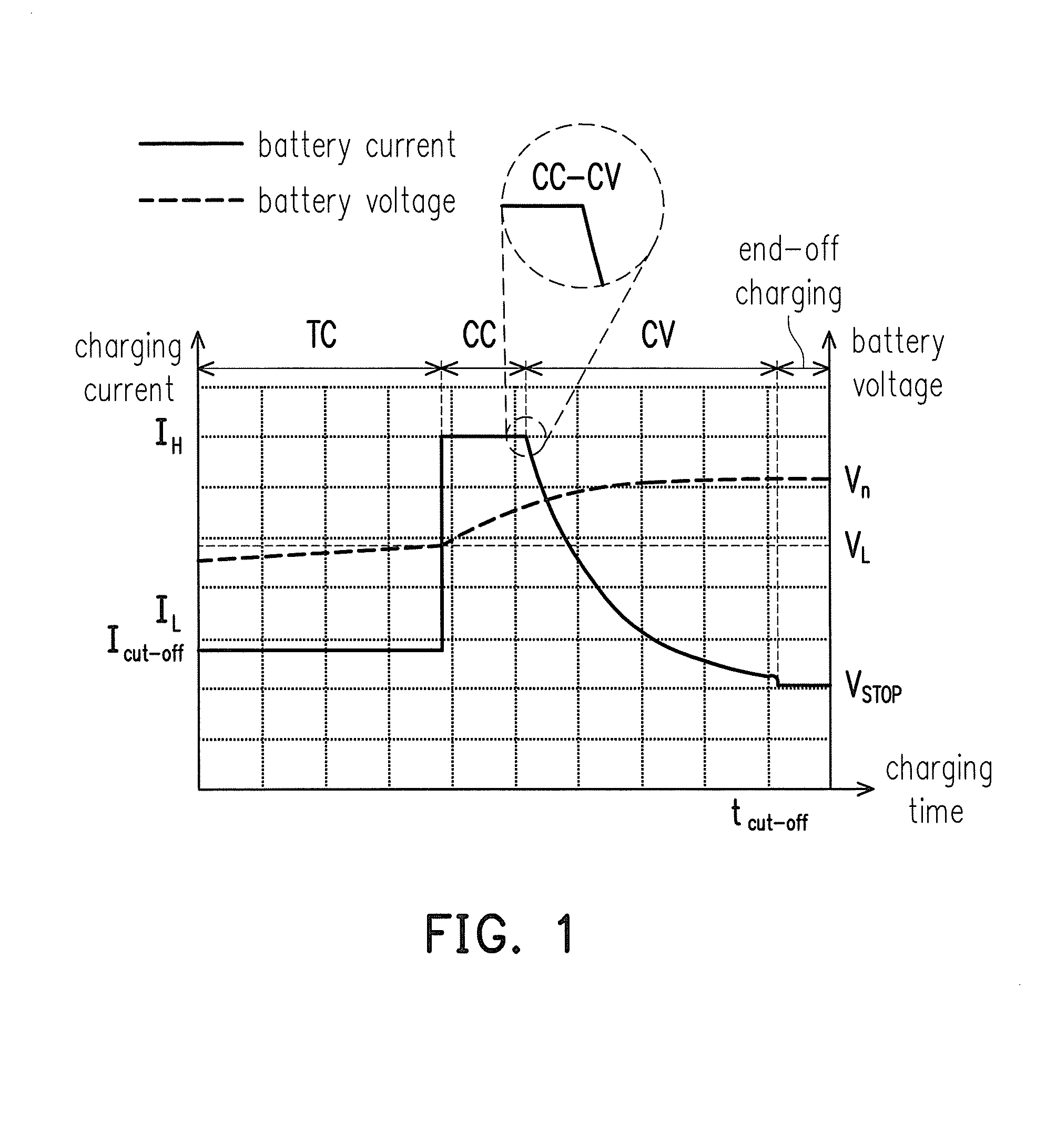
Furthermore, take the general linear Li-Ion charger as an example, due to the internal resistance of the battery, when the system switches between each modes, such as small current mode transfers to constant current (CC) mode, or constant current mode transfer to constant voltage (CV) mode, if we do not do a good job related to circuit switching mechanism, which may lead to oscillation phenomenon during the circuit switching, and thus damage to the charger and the battery.
Besides, after the battery is fully charged, if the chargers failed to timely close the charging operation, it will lead to the battery overcharging which may greatly reduce the battery life, if there is no protecting battery mechanism, it is easy to produce a great damage to the battery, on the one hand, the battery capacity is no longer as usual, on the other hand, the battery elimination rate may also increase, and the more eliminated battery may also cause problems, such as junk issues, or environmental pollution, etc.

Method used


Image

  • Charging structure
  • Charging structure
  • Charging structure

Examples


Embodiment Construction

[0019]Reference will now be made in detail to the present preferred embodiments of the invention, examples of which are illustrated in the accompanying drawings. Wherever possible, the same reference numbers are used in the drawings and the description to refer to the same or like parts.

[0020]First, FIG. 3 is a block diagram illustrating a charging structure according to an embodiment of the invention. Referring to FIG. 3, the charging structure 10 includes a power supply device 104, a charging management device 100, and a rechargeable battery 102. In the present embodiment, the power supply device 104 may be a charger, a mobile power, or a fuel cell battery module, etc. with at least a power output function, but the invention is not limited thereto. Besides, the charging management device 100 and the rechargeable battery 102 may be disposed in different types of the terminal device, such as an electric car or handheld device (for example, a Smart phone, a tablet, etc.), but the inv...


PUM


Abstract

A charging structure including a power supply device, a rechargeable battery and a charging management device is provided. The power supply device is configured to provide a system voltage. The charging management device is configured to switch a corresponding charging mode according to the voltage level of the positive end of the rechargeable battery. The charging management device stops charging action when a charging current for charging the rechargeable battery drops down to a pre-set current value.

Description

BACKGROUND[0001]1. Field of the Invention[0002]The invention generally relates to a charging structure, and in particular, to a charging structure with an analog smooth transition circuit (ASTC) and an end of charge (EOC) circuit.[0003]2. Description of Related Art[0004]In this green energy technology age, electronic products and environmental protection must be linked to each other, and the battery is no exception, so when charging the battery charger must follow this principle. Frequency of use of a battery is about 500 to 1000 times, the capacity of the battery will be less and less with the number of charge-discharge cycles increases. Furthermore, take the general linear Li-Ion charger as an example, due to the internal resistance of the battery, when the system switches between each modes, such as small current mode transfers to constant current (CC) mode, or constant current mode transfer to constant voltage (CV) mode, if we do not do a good job related to circuit switching me...

Claims


Application Information

Patent Timeline
IPC IPC(8): H02J7/00
CPCH02J7/0052H02J7/007H02J7/00712
Inventor HUNG, CHUNG-CHIHCHEN, YI-AN
Owner WINBOND ELECTRONICS CORP
Learn More