Wireless communication apparatus and electronic apparatus

a communication apparatus and electronic technology, applied in the direction of antennas, antenna details, antenna earthings, etc., can solve the problems of significant reduction of communicable distance or effective data transfer rate, increased risk of cataracts, and decreased radiation efficiency of electromagnetic waves at communication frequencies, so as to reduce the bias of directivity of electromagnetic waves, enhance the radiation efficiency of electromagnetic waves, and reduce the sar value

Active Publication Date: 2016-08-18
CANON KK
View PDF3 Cites 5 Cited by
  • Summary
  • Abstract
  • Description
  • Claims
  • Application Information

AI Technical Summary

Benefits of technology

[0009]In view of the above, it is an object of the present invention to decrease a SAR value while decreasing a bias of directivity of an electromagnetic wave in an antenna and enhancing radiation efficiency of the electromagnetic wave at a communication frequency at the same time.
[0011]Further, according to another embodiment of the present invention, there is provided a wireless communication apparatus, including: an antenna including: an antenna element having one end portion that is opened; and a ground conductor to be used as a ground, to which another end portion of the antenna element is connected; a wireless device connected to the antenna; and a blocking member, which is arranged so as to be opposed to the antenna, and is configured to block an electromagnetic wave, wherein the blocking member is arranged so as to, in plan view from the blocking member side in a direction toward the antenna, avoid overlapping at least a position where an electric field strength of the antenna is largest.

Problems solved by technology

There has been pointed out a possibility of, for example, an increased risk of developing cataract due to this local temperature increase in the human body.
However, with the configuration of Japanese Patent Application Laid-Open No. 2005-45646, although the SAR value is decreased through the arrangement of the metal plate, there is a problem in that radiation efficiency of the electromagnetic wave at a communication frequency is decreased due to resonance between the metal plate and the antenna.
However, under a situation in which one-to-one communication is performed between, for example, a camera and a PC, when a communication partner exists in the direction of the metal plate, there is a problem in that a communicable distance or an effective data transfer rate is significantly decreased due to a bias of the directivity of the electromagnetic wave in the antenna.

Method used


Image

  • Wireless communication apparatus and electronic apparatus
  • Wireless communication apparatus and electronic apparatus
  • Wireless communication apparatus and electronic apparatus

Examples


first embodiment

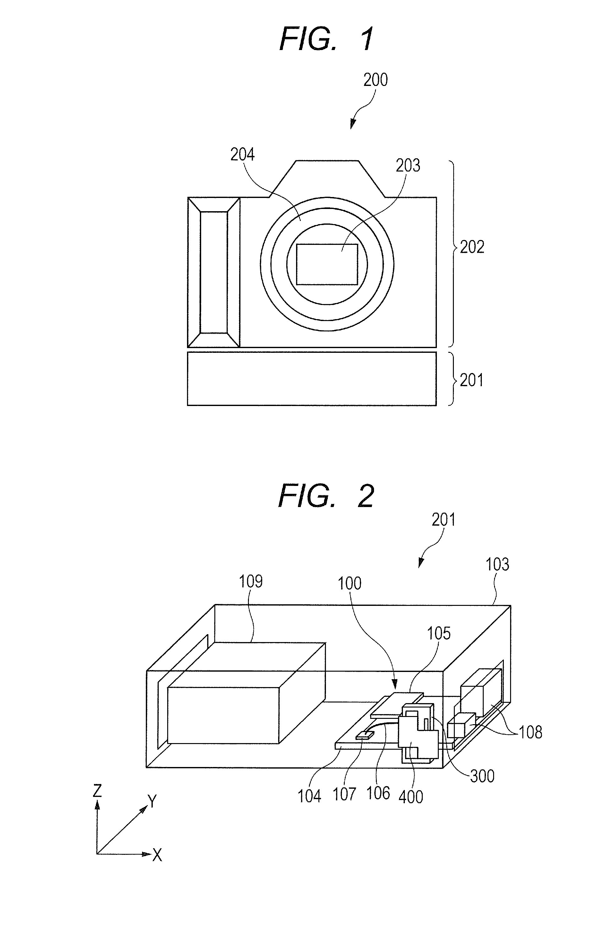
[0060]FIG. 1 is an explanatory diagram for illustrating a schematic configuration of an image pickup apparatus as an example of an electronic apparatus according to a first embodiment of the present invention. The image pickup apparatus 200 includes a camera main body 202 and a wireless communication apparatus (wireless transmitter) 201 mounted to the camera main body 202. The camera main body 202 includes an image pickup element 203. A replaceable lens (not shown) is mounted to a mount 204 of the camera main body 202. An image signal generated based on an image picked up by the image pickup element 203 is output to the wireless communication apparatus 201.

[0061]The wireless communication apparatus 201 wirelessly transmits the image signal to a camera (not shown) or a PC (not shown) by a wireless LAN, Bluetooth (trademark), or the like. For wireless communication of the wireless LAN, Bluetooth (trademark), or the like, a radio wave of a 2.4 [GHz] band (e.g., a 2.45 [GHz] band) or a ...

example 1

[0107]As an example of the antenna 300 and the metal plate 400 according to the embodiment described above, the following numerical experiment was conducted. In this experiment, power supplied to the antenna 300 that is the inverted F antenna was set to 13 [dBm], and a communication frequency was set to 2.45 [GHz]. MW-STUDIO, which is an electromagnetic field simulator manufactured by AET, INC., was used for calculation.

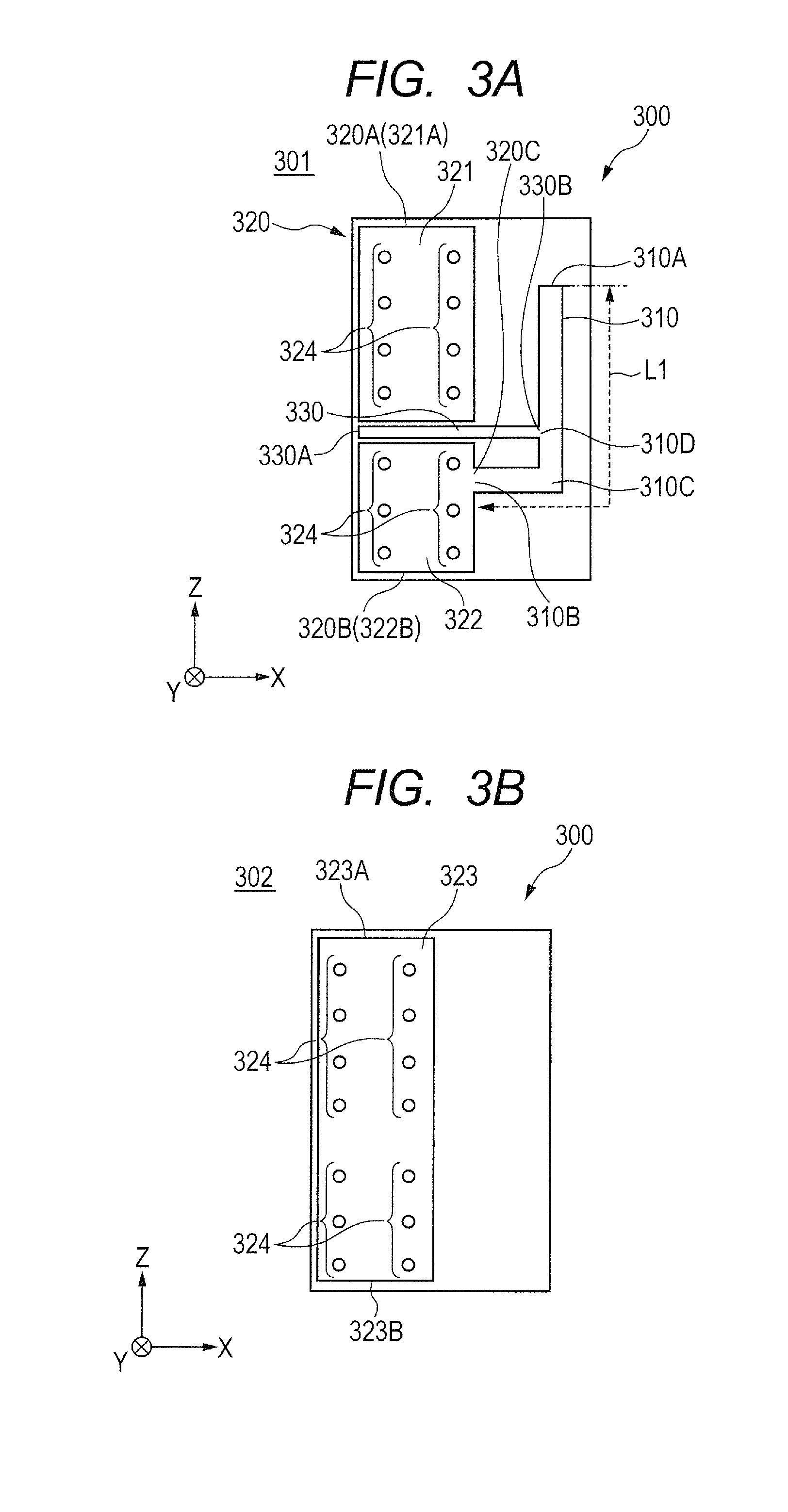
[0108]FIG. 8A and FIG. 8B are external views for illustrating calculation models for the antenna 300 according to Example 1 of the present invention. The antenna 300 is formed of the printed wiring board. FIG. 8A is an external view for illustrating the calculation model for the conductor layer 301, which serves as the first conductor layer of the antenna 300 formed of the printed wiring board. FIG. 8B is an external view for illustrating the calculation model for the conductor layer 302, which serves as the second conductor layer of the antenna 300 formed of the pri...

experimental example 1-1

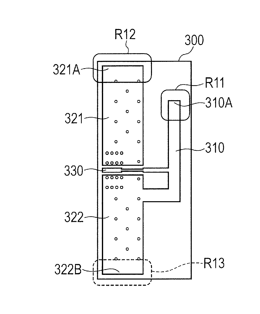
[0129]FIG. 14 is an external view for illustrating a calculation model for the metal plate and the antenna according to Example 1. As illustrated in FIG. 14, in the metal plate 400, cutouts are formed on the one end portion 310A side of the antenna element 310, the end portion 321A side of the ground pattern 321, and the end portion 322B side of the ground pattern 322. A cutout length of the cutout formed on the one end portion 310A side of the antenna element 310 in the arrow Z direction is represented by Z1. A cutout length of the cutout formed on the end portion 321A side of the ground pattern 321 in the arrow Z direction is represented by Z3. A cutout length of the cutout formed on the end portion 322B side of the ground pattern 322 in the arrow Z direction is represented by Z2. A cutout length of a cutout formed on the side opposite to the one end portion 310A of the antenna element 310 in the arrow Z direction is represented by Z4.

[0130]As described above, the regions of the a...


PUM


Abstract

There is provided a wireless communication apparatus, including: an antenna including: an antenna element having one end portion that is opened; and a ground conductor to be used as a ground, to which another end portion of the antenna element is connected; a wireless device connected to the antenna; and a blocking member, which is arranged so as to be opposed to the antenna, and is configured to block an electromagnetic wave, wherein the blocking member is arranged so as to, in plan view from the blocking member side in a direction toward the antenna, avoid overlapping at least the one end portion of the antenna element and overlap the another end portion of the antenna element.

Description

BACKGROUND OF THE INVENTION[0001]1. Field of the Invention[0002]The present invention relates to a wireless communication apparatus including a blocking member configured to block an electromagnetic wave radiated from an antenna, and an electronic apparatus including a wireless communication apparatus.[0003]2. Description of the Related Art[0004]In recent years, a wireless communication apparatus having a wireless communication function has been mounted to an electronic apparatus that is an image pickup apparatus (e.g., a digital camera), which enables the image pickup apparatus to wirelessly transmit a signal of a picked-up image to another camera or a PC (Personal Computer) by a wireless LAN (Local Area Network), Bluetooth (trademark), or the like. In wireless communication by a wireless LAN, Bluetooth (trademark), or the like, a radio wave of a 2.4 [GHz] band or a 5 [GHz] band is used. A wireless communication apparatus is built into an electronic apparatus in some cases. In othe...

Claims


Application Information

Patent Timeline
Patent Type & Authority Applications(United States)
IPC IPC(8): H04B1/3827H01Q9/42H01Q1/52H01Q1/22H01Q1/48
CPCH04B1/3838H01Q1/2291H01Q9/42H01Q1/528H01Q1/48
Inventor AOKI, MAKOTOABE, DAIKI
Owner CANON KK
Why Eureka
Try Eureka