
Spring forming device and forming method therefor

a technology of forming device and spring, which is applied in the direction of wire spring, other domestic objects, electric/magnetic/electromagnetic heating, etc., can solve the problems of low shape flexibility and difficulty in forming, and achieve uniform heating

Inactive Publication Date: 2016-08-25
NHK SPRING CO LTD
View PDF1 Cites 8 Cited by
  • Summary
  • Abstract
  • Description
  • Claims
  • Application Information

AI Technical Summary

Benefits of technology

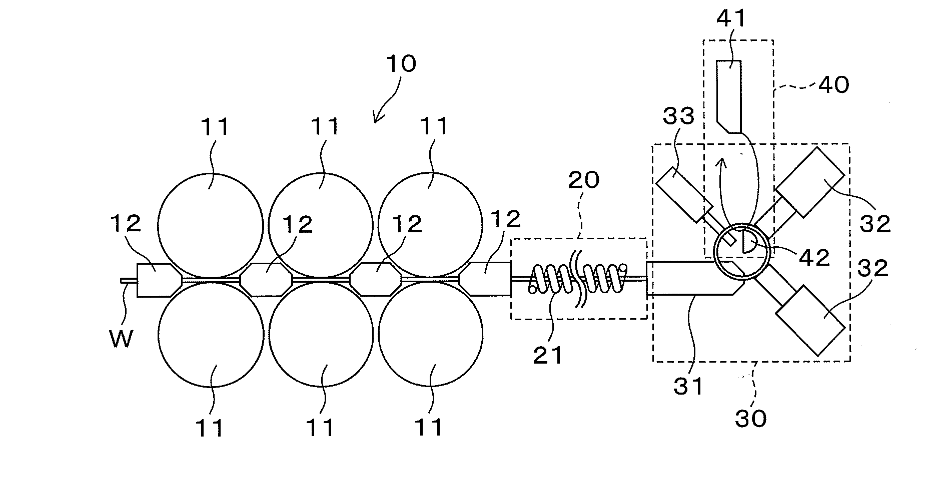
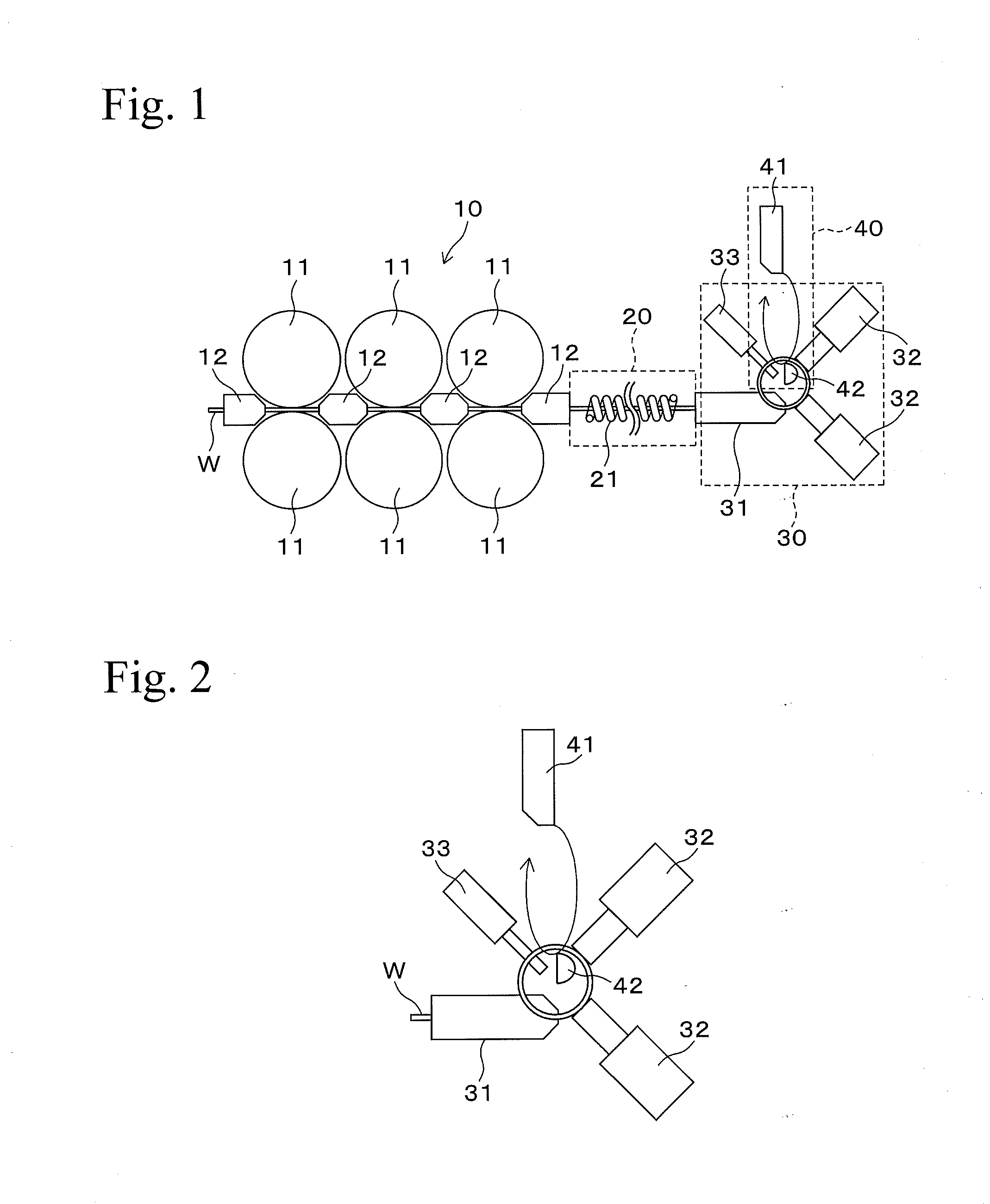
The present invention is related to a cutting method for continuous operation, which prevents non-uniform heating of steel wire and produces a uniform heating temperature. This is achieved by using a high-frequency heating mechanism with a coil length of 100 to 350 mm, which ensures sufficient heating to the inside of the steel wire. The heated steel wire can be coiled and hardened to produce a spring with superior durability. The cutting blade follows tracks with a speed close to the speed of the coiled steel wire, which prevents stopping of the feeding of the steel wire during cutting and allows for more uniform heating.

Problems solved by technology

This is one reason it is difficult to form since workability in the cold-forming is low due to thick wires being used.
Therefore, the flexibility of the shape is low, and moreover, the core bar must be arranged in each product.

Method used


Image

  • Spring forming device and forming method therefor
  • Spring forming device and forming method therefor
  • Spring forming device and forming method therefor

Examples


example 1

[0048]Crystal grain sizes and coil outer diameters of coiled springs which were produced while feeding speed in cutting off of steel wire was changed from 8 to 50 m / min, are shown in Table 1. In the Examples of the present invention, in the case in which feeding speed (a) in cutting off of steel wire was the same as feeding speed (b) in forming of steel wire, and in the case in which feeding speed (a) in cutting off of steel wire was 90% of feeding speed (b) in forming of steel wire, there was no difference between crystal grain size at both edge portions of a coil and crystal grain size at an effective portion of the coil, and grain size number thereof was 12.2. In addition, coil outer diameters at the both edge portions and the effective portion of the coil were the same. Furthermore, in the case in which feeding speed (a) in cutting off of steel wire was 50% of feeding speed (b) in forming of steel wire, the grain size number was 10.5 and was sufficient, and a difference of coil ...

example 2

[0050]Roundness of coil diameters at a coiling start side terminal of coiled springs, produced while Vc / Vw was changed from 1.00 to 3.00, is shown in Table 2.

TABLE 2WirediameterVcVwVc / RoundnessNos.(mm)(m / min)(m / min)Vw(mm)NoteExamples1444401.101.0002450401.251.0003470401.751.00044100402.501.0005250401.251.0006550401.251.0007475501.501.00084120403.001.000Overspecification9442401.050.995TerminaldeformationComparative10440401.00—Not coilingExample(buckling)

[0051]In Examples 1 to 9 in which Vc / Vw was 1.05 to 2.50, in the case in which the steel wire diameter was 2 to 5 mm (in the present invention, it was a diameter in the case in which roundness was calculated from a cross sectional area of the steel wire, and it contained the case in which a circle equivalent diameter including a non-circular cross section such as a rectangle, an ellipse, etc., was 2 to 5 mm), the coiling could be carried out when the roundness was 0.995 to 1.000. In particular, in Examples 1 to 8 in which Vc / Vw was 1....


PUM

PropertyMeasurementUnit
space distanceaaaaaaaaaa
lengthaaaaaaaaaa
lengthaaaaaaaaaa

Abstract

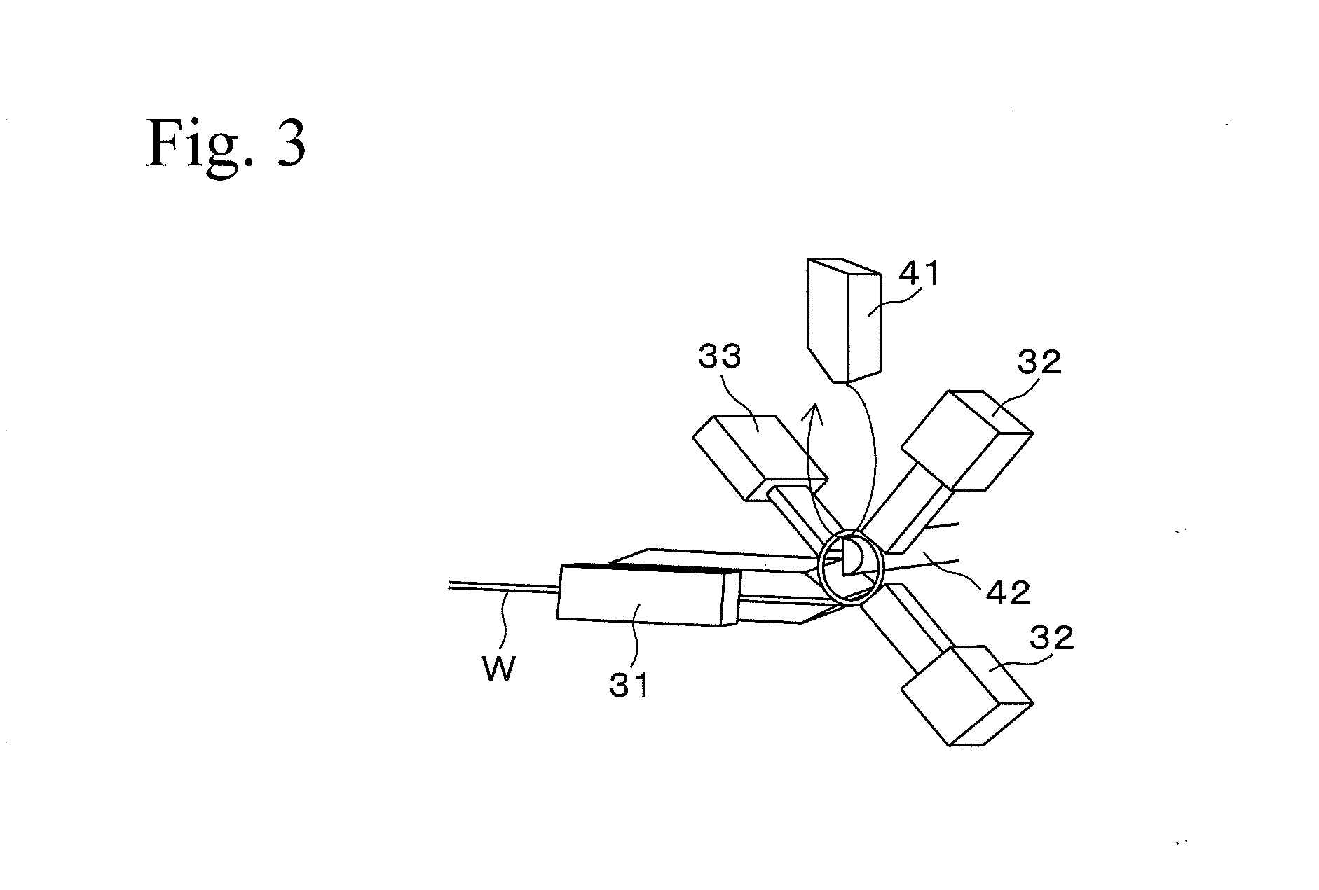
A spring forming device in which the steel wire can be continuously cut off without stopping the feeding of the steel wire in cutting, and in which the steel wire can be uniformly heated, is provided. The spring forming device has a wire supplying mechanism for supplying a steel wire using a plurality of feeding rollers, a heating mechanism for heating the steel wire, a coiling mechanism for forming in a coil state the heated steel wire, and a cutting mechanism for cutting the steel wire coiled at a given number of turns off the steel wire remained backward. A cutting blade of the cutting mechanism follows tracks having a speed Va that moves to the receiving blade and a speed Vc that moves in an axial direction of the coiled steel wire, in cutting of the steel wire.

Description

BACKGROUND OF THE INVENTION[0001]1. Technical Field[0002]The present invention relates to a spring forming device in which a spring such as a coil spring is continuously hot-formed while feeding a steel wire, and in particular, it relates to a technique in which uneven heating of the steel wire is decreased by continuously cutting the steel wire without stopping the feeding thereof.[0003]2. Background Art[0004]Recently, in transportation equipment, in particular, in an automobile, requirements for reducing fuel consumption are annually increased in consideration of global warming, and size reduction and weight reduction of automobile parts is required more stringently than ever. In order to satisfy this requirement for size reduction and weight reduction, for example, in compression coil spring parts such as a valve spring used in an engine, a clutch damper spring used in a clutch, etc., attempts were made up until now to improve fatigue resistance or settling resistance, which are ...

Claims


Application Information

Patent Timeline
Patent Type & Authority Applications(United States)
IPC IPC(8): B21F35/00H05B6/10B21F23/00B21F3/06B21F11/00
CPCB21F23/00B21F35/00H05B6/101B21F11/005B21F99/00B21F3/06
Inventor TAKAHASHI, KEITASHIRAISHI, TOHRUONO, YUICHIRONAGASAWA, KAORU
Owner NHK SPRING CO LTD
Learn More