Needle steering by shaft manipulation

a technology of shaft manipulation and needle steering, which is applied in the field of needle steering devices, to achieve the effect of monitoring patient respiration and sufficiently stiff control

Active Publication Date: 2016-09-01
TECHNION RES & DEV FOUND LTD
View PDF4 Cites 168 Cited by
  • Summary
  • Abstract
  • Description
  • Claims
  • Application Information

AI Technical Summary

Benefits of technology

[0022]Control of one or more joints is useful for solution of the respiration gait problem (respiration compensation), where the robot should move synchronously with movements of the patient's body. An additional function of the semi-active arm may be to monitor the respiration of the patient. The semi-active arm reduces the need for placing external sensors on the patient's skin, as is done in prior art methods, in order to monitor the stages of the breath cycle of the patient. Since the robotic needle manipulator maintains contact with the patient's chest, its sensors are able to define the breath cycle of the patient.
[0023]A particularly useful configuration of the support arm is to provide it with positive control in the direction perpendicular to the patient's body surface, such as by use of a spring, such that it exerts sufficient pressure that the robotic needle manipulator remains in contact with the patient's skin, yet allows the robotic needle manipulator to rise and fall with the patient's breathing cycle. At the same time, the other directions of freedom of the robotic needle manipulator control system may advantageously be maintained sufficiently stiffly controlled that the robotic needle manipulator remains nominally constrained by the support arm to its predetermined position on the subject's body at the needle insertion point, yet allows some level of freedom of movement should the patient move laterally during the procedure due to coughing or discomfort or the like.

Problems solved by technology

However, use of a robotic platform with more than 4 degrees of freedom may also be advantageous, though the use of the direction of freedom in the direction parallel to the needle will not generally be used for inserting the needle, because the large travel generally required for inserting the needle may conflict with the need to maintain a low profile workspace of the robotic needle manipulator.

Method used


Image

  • Needle steering by shaft manipulation
  • Needle steering by shaft manipulation
  • Needle steering by shaft manipulation

Examples


Embodiment Construction

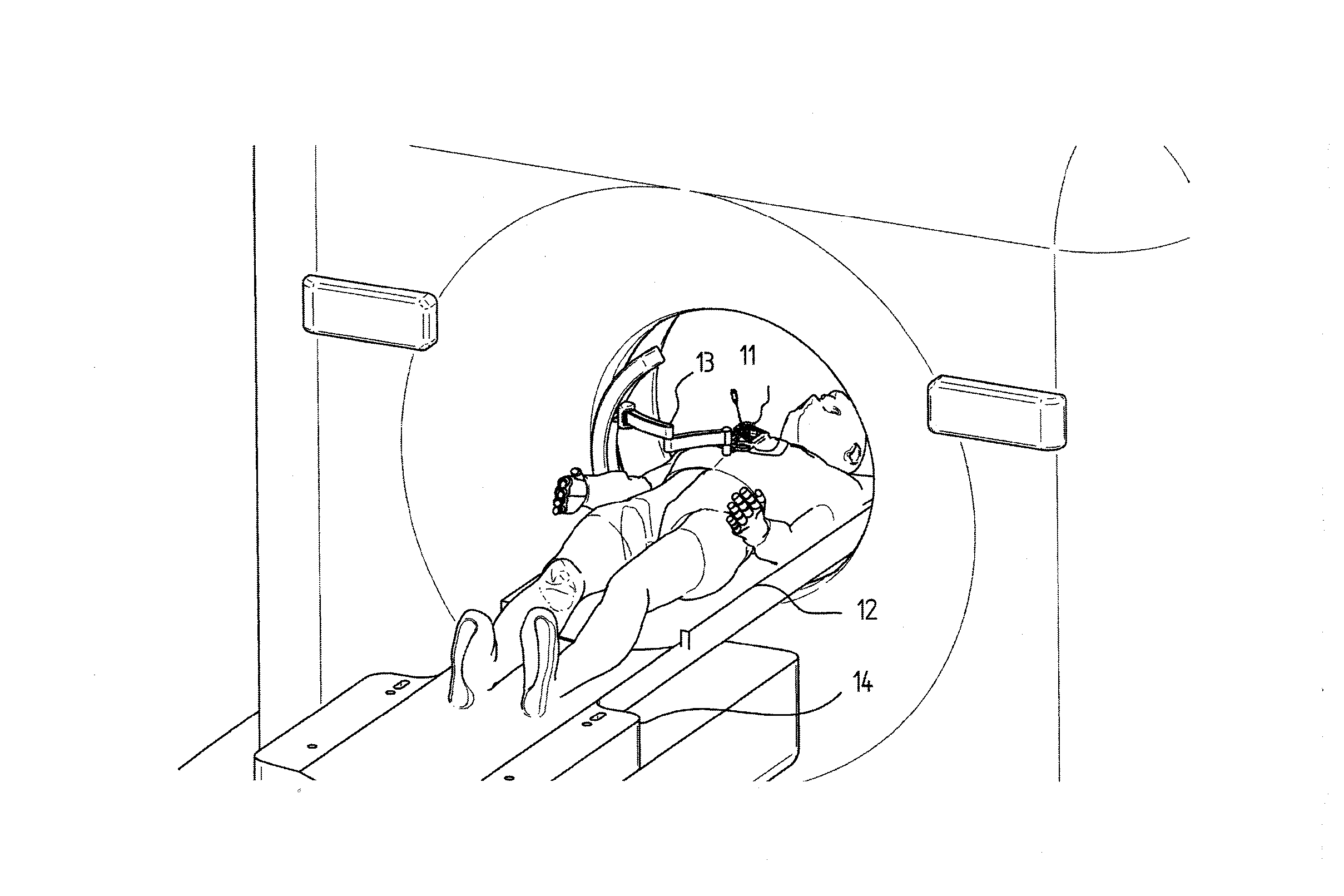
[0057]Reference is first made to FIGS. 1 and 2 which show the overall view of a system used to manipulate the needle under the guidance of an imaging system, such as CT or MRI guidance. However, it is to be understood that the needle steering manipulation technique and the needle manipulating robot is not limited to use with CT or MRI imaging modality, but can be used with any existing imaging modality such as Ultrasound, PET, or the like.

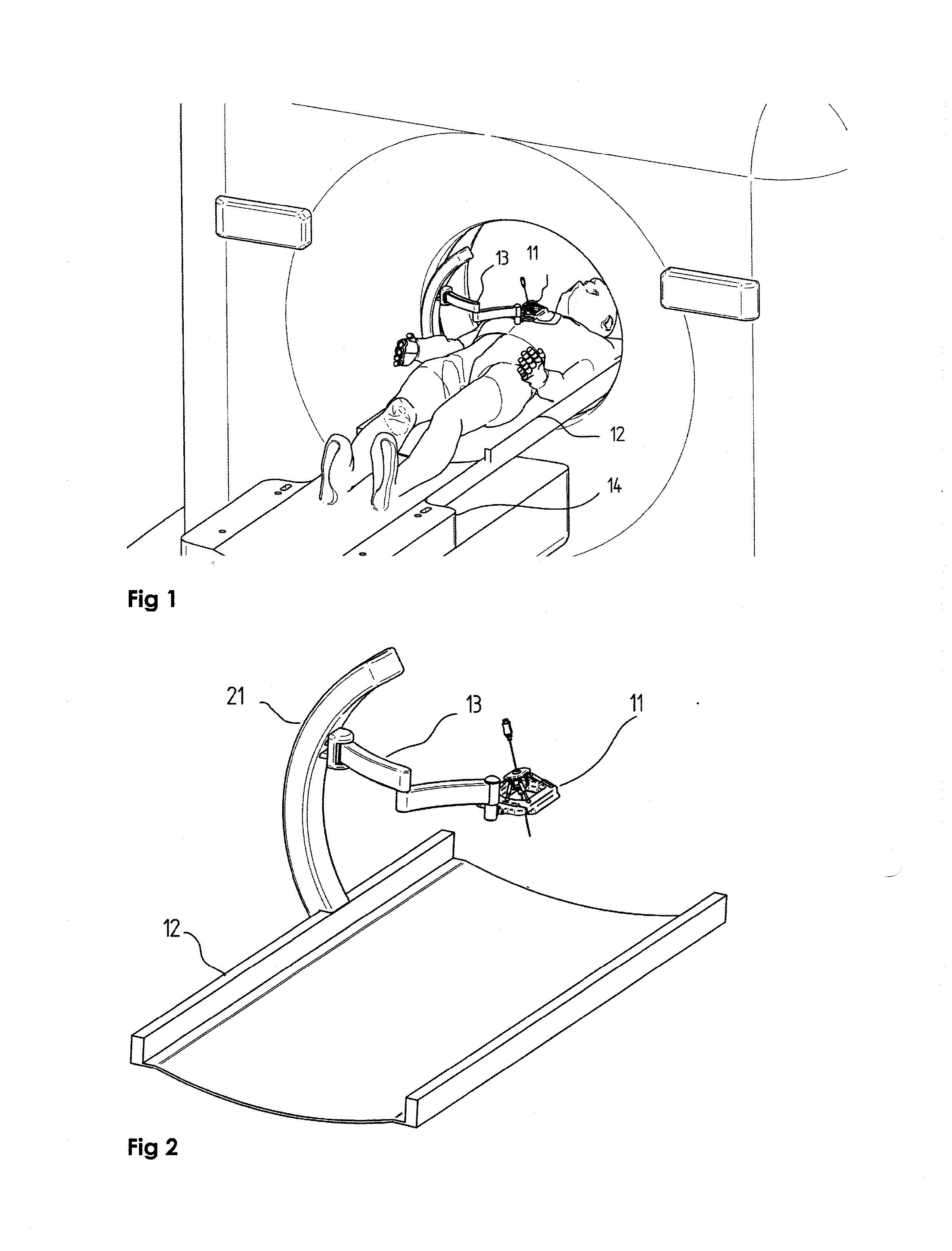
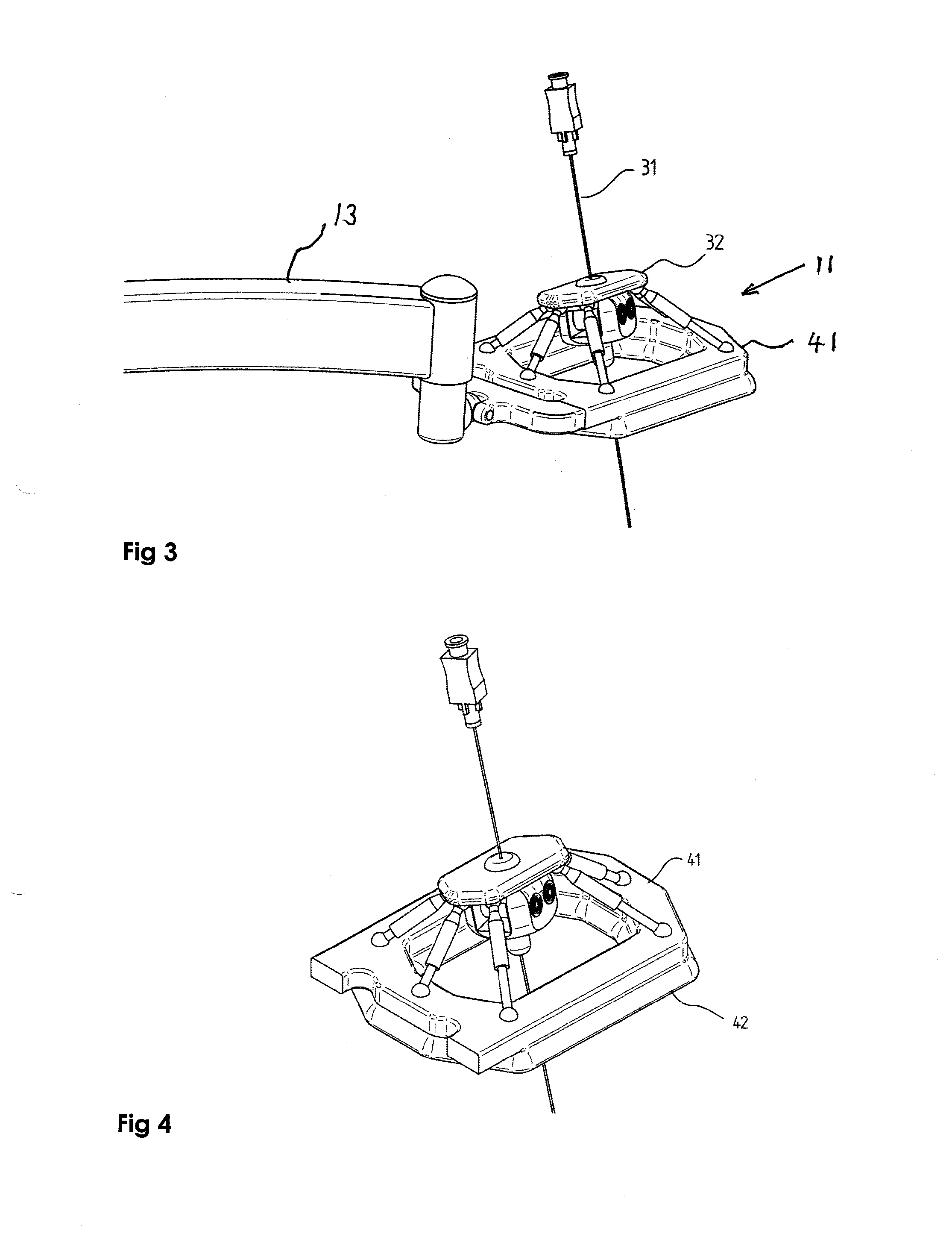
[0058]FIG. 1 shows an exemplary system mounted on a CT system. The system does not need to be connected to the CT system directly. The robotic needle manipulator 11 may be connected to the base element plate 12 via a semi-active arm 13, which may be connected to the base element via an arched support arm 21. The base element may be placed on the imaging system bed 14 and moves together with the imaging system bed. Alternatively, the support arch could be mounted directly on the imaging system bed.

[0059]Reference is now made to FIG. 2 where the comp...


PUM


Abstract

A method and apparatus for steering of a flexible needle into tissue using a steering robotic platform for manipulation of the needle shaft, and by use of a semi-active arm for locating and orienting of the steering robot on the patient's body. As opposed to other steering methods, the robot does not hold the base of the needle, which is its proximal region, but rather grips the shaft of the needle by means of a manipulatable needle gripping device, near its distal end. The needle gripper attached to the robotic platform may be equipped with a traction assembly to provide motion to the needle in its longitudinal direction, such that it co-ordinates the entry of the needle with the desired entry angle. The gripping of the needle at its distal end, close to its insertion point, provides the needle manipulator with a low profile, with concomitant advantages.

Description

FIELD OF THE INVENTION[0001]The present invention relates to the field of devices for needle steering and their use in image-guided robotic needle steering.BACKGROUND OF THE INVENTION[0002]Many routine treatments employed in modern clinical practice involve percutaneous insertion of needles and catheters for biopsy and drug delivery and other therapies. The aim of a needle insertion procedure is to place the tip of an appropriate needle safely and accurately in a target region, which could be a lesion, organ or vessel. Examples of treatments requiring needle insertions include vaccinations, blood / fluid sampling, regional anesthesia, tissue biopsy, catheter insertion, cryogenic ablation, electrolytic ablation, brachytherapy, neurosurgery, deep brain stimulation and various minimally invasive surgeries.[0003]Guidance and steering of needles in soft tissue is a complicated task that requires good 3-D coordination, knowledge of the patient anatomy and a high level of experience. Therefo...

Claims


Application Information

Patent Timeline
Patent Type & Authority Applications(United States)
IPC IPC(8): A61B34/30A61B90/11
CPCA61B34/30A61B90/11A61B2090/374A61B2090/3762A61B90/37A61B2034/304A61B2017/3409
Inventor GLOZMAN, DANIELDASKAL, GONENSHOHAM, MOSHEARAD, MICHAELPINSKY, YOAV
Owner TECHNION RES & DEV FOUND LTD
Why Eureka
Try Eureka