
Parallel mechanism based automated fiber placement system

a technology of automatic fiber placement and parallel mechanism, which is applied in the direction of manipulators, program-controlled manipulators, domestic applications, etc., can solve the problems of serial robots generally having low stiffness, large inertia, affecting force and precision performance, etc., and achieve good kinematics performance

Active Publication Date: 2016-09-01
KHALIFA UNIV OF SCI & TECH +1
View PDF2 Cites 22 Cited by
  • Summary
  • Abstract
  • Description
  • Claims
  • Application Information

AI Technical Summary

Benefits of technology

The present invention proposes a 2T2R parallel mechanism for automated fiber placement. The mechanism design is based on a 2RPS-2UPS topology, with the main objective of finding the optimal locations of two UPS limbs to give a large singularity-free workspace and good kinematics performance. An angle-based 3D space is proposed to have a uniform unit by representing the translations in rotations. An optimized mechanism configuration is found and the effect of joint components is also demonstrated, resulting in a practical design for AFP and other applications. The technical effect is that a parallel robot design is proposed for automated fiber placement, which can decrease the weight of lay-up heads, offer multiple support limbs with low inertia, high structure stiffness, good positioning accuracy, and high speeds, providing a solution for high-compact-force applications such as AFP.

Problems solved by technology

Although many robot based Automated Fiber Placement (AFP) systems have been proposed and used in composites manufacturing industry, but parallel robots are still not used in composites manufacturing.
However, serial robots generally have low stiffness and large inertia due to their serially connected structure, which affects their force and precision performance in high-compact-force applications, like AFP.

Method used


Image

  • Parallel mechanism based automated fiber placement system
  • Parallel mechanism based automated fiber placement system
  • Parallel mechanism based automated fiber placement system

Examples


Embodiment Construction

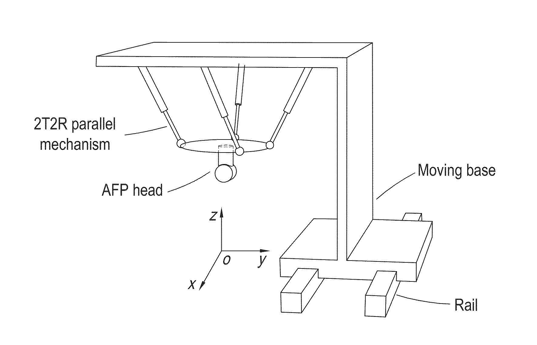
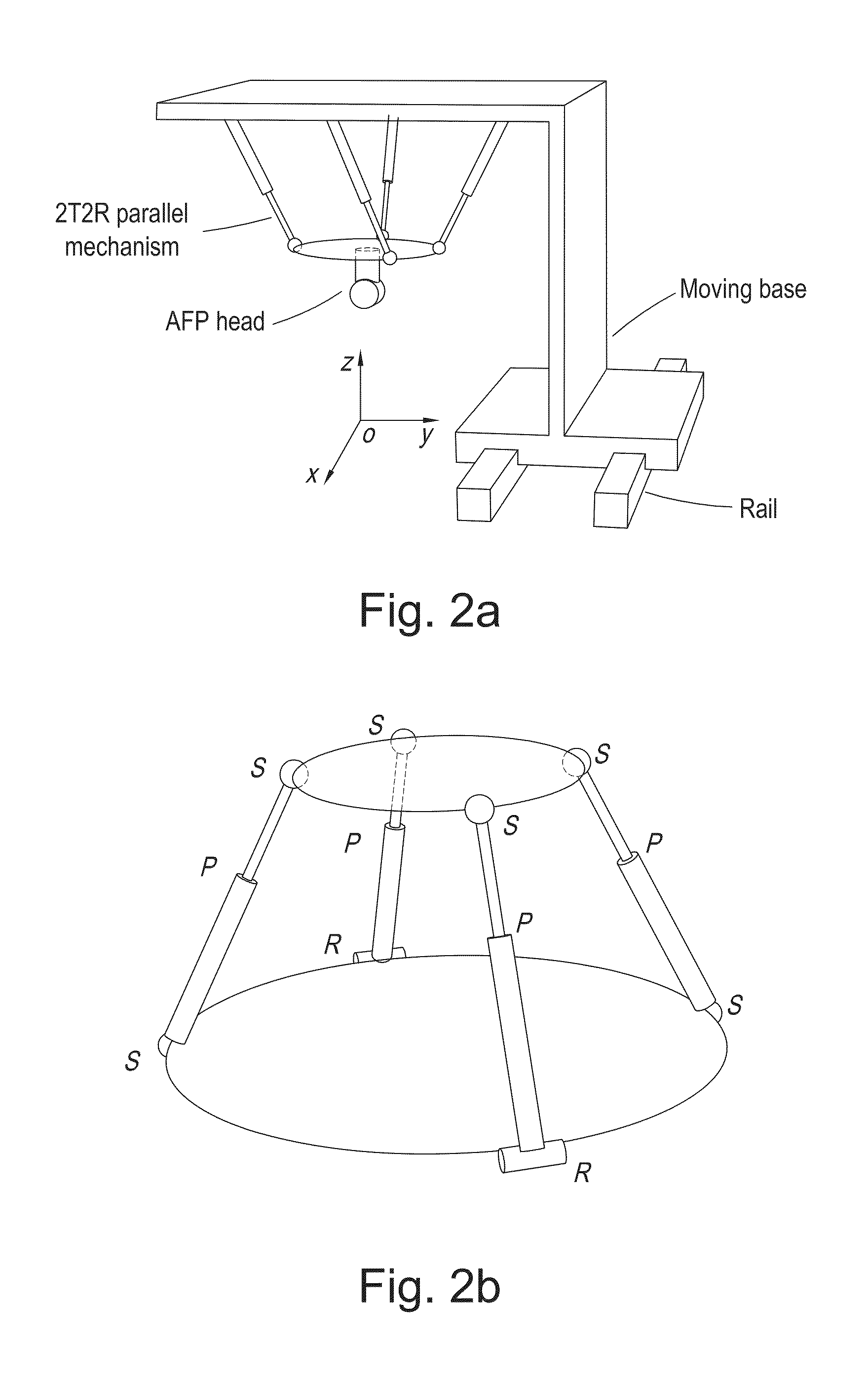
[0044]2. A 2T2R Parallel Mechanism Based AFP System

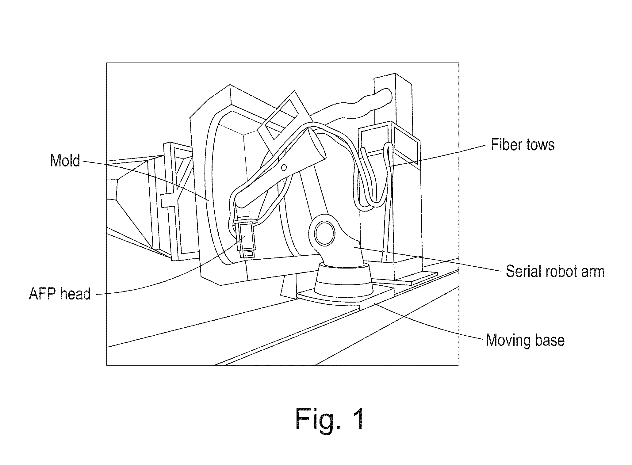
[0045]In AFP systems, fiber tows are guided by a fiber-processing head attached to the end-effector of a robot and carefully placed following a pre-defined robot trajectory as in FIG. 1. To tack the tows on the mold, they are heated and compacted at the same time when the robot is moving. Since the ratio of the mass of payload over the mass of the robot is typically small for 6DOF serial robots, like the KUKA robot in FIG. 1, the ratio is about 210 kg / 1150 kg=0.18, the ratio can be larger than 10 for parallel robots. In this case, for the same payload of 210 kg, a 21 kg parallel robot might be enough to support it. Following this, the advantage is obvious considering the space occupation and system cost. Although parallel robots suffers from the smaller workspace than serial ones, a moving base is generally used to enlarge the workspace and it is also common for the serial robots in the industry, like the one in FIG. 1.

[0046]Conside...


PUM

PropertyMeasurementUnit
Angleaaaaaaaaaa
Poweraaaaaaaaaa

Abstract

The present invention introduces a new concept of applying a parallel mechanism in automated fiber placement for aerospace part manufacturing. The proposed system requirements are 4DOF parallel mechanism consisting of two RPS and two UPS limbs with two rotational and two translational motions. Both inverse and forward kinematics models are obtained and solved analytically. Based on the overall Jacobian matrix in screw theory, singularity loci are presented and the singularity-free workspace is correspondingly illustrated. To maximize the singularity-free workspace, locations of the two UPS limbs with the platform and base sizes are used in the optimization which gives a new design of a 4DOF parallel mechanism. A dimensionless Jacobian matrix is also defined and its condition number is used for optimizing the kinematics performance in the optimization process. A numerical example is presented with physical constraint considerations of a test bed design for automated fiber placement.

Description

FIELD OF THE INVENTION[0001]The present invention generally relates to parallel mechanism in automated fiber placement for aerospace part manufacturing.BACKGROUND OF THE INVENTION[0002]Automated fiber placement (AFP) is an important manufacturing process in composite aerospace part manufacturing and has attracted much interest since future aircraft programs, such as the Boeing 787 and Airbus A350XWB, contain more than 50% by weight of advanced composite components. Also, the use of robot manipulators increases the flexibility of the fiber placement process and allows for the fabrication of more complex structures. Existing AFP research discusses productivity, steering and control, processing conditions, materials, layup modeling and simulation, and functional integration. Robotics work mainly focuses on path planning for AFP while typically a point-cloud is generated for the AFP head to follow to lay the material onto the mold.[0003]Although many robot based AFP systems have been pr...

Claims


Application Information

Patent Timeline
IPC IPC(8): B25J9/00B29C70/38B29C70/06B25J9/16B25J11/00
CPCB25J9/006B25J9/1697B25J11/005B25J11/0055B25J11/0075B29C70/06B29L2031/3076Y10S901/42Y10S901/43B29K2105/0881B29K2105/06B29K2101/12B29K2101/10B29C70/382B25J9/0072B29C70/386
Inventor GAN, DONGMINGDAI, JIAN S.DIAS, JORGEUMER, REHANSENEVIRATNE, LAKMAL
Owner KHALIFA UNIV OF SCI & TECH
Learn More