Controller for vehicle

Active Publication Date: 2016-09-01
MITSUBISHI MOTORS CORP
View PDF2 Cites 6 Cited by
  • Summary
  • Abstract
  • Description
  • Claims
  • Application Information

AI Technical Summary

Benefits of technology

[0014]According to the present invention, operation of the waste gate valve is controlled in response to the regenerative power generation amount.
[0015]Specifically, when the rotary electric machine performs the regenerative power generation, the waste gate valve is allowed to operate toward its open side to allow exhaust gas discharged from the internal combustion engine to flow downstream of the turbine through the bypass passage. As a result, a flow rate of exhaust gas injected into the turbine is reduced, so that it is possible to reduce pressure of the exhaust gas discharged from the internal combustion engine, or exhaust pressure.
[0016]Thus, as th

Problems solved by technology

However, generating power not only for running the vehicle but also for driving the g

Method used


Image

  • Controller for vehicle
  • Controller for vehicle
  • Controller for vehicle

Examples


Embodiment Construction

[0021]Hereinafter, an embodiment of the present invention will be described on the basis of the accompanying drawings.

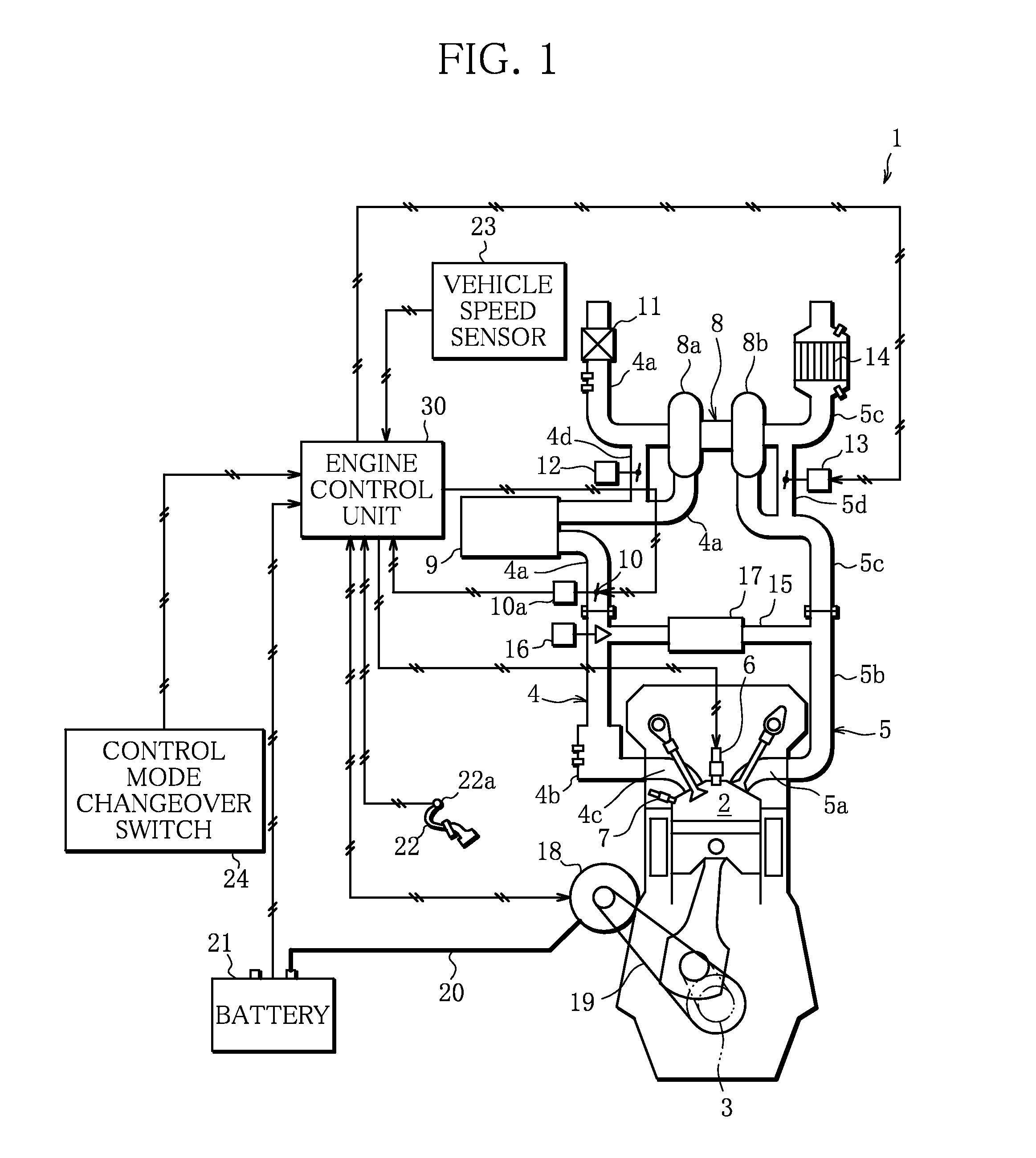
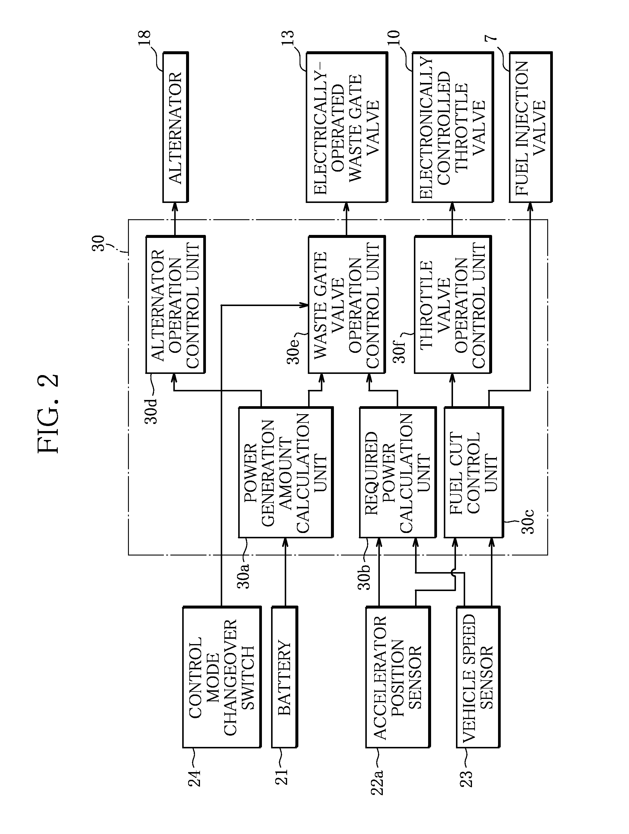
[0022]FIG. 1 is a schematic diagram of an engine 1 to which the controller for a vehicle is applied. A thick solid line in FIG. 1 shows an electric power supply wiring 20 through which electric power is supplied from an alternator 18 to a battery 21. In addition, FIG. 2 is a block diagram showing an internal configuration of an engine control unit 30 in the controller for a vehicle.

[0023]As shown in FIG. 1, the engine (internal combustion engine) 1 is a multi-cylinder direct-injection gasoline engine mounted on a vehicle (not shown), and that specifically has a structure in which fuel is supplied to a fuel injection valve (fuel supply unit) 7 of each of cylinders and the fuel injection valve 7 can inject the fuel into a combustion chamber 2 of each of the cylinders at any timing and amount. As shown in FIG. 1, the engine 1 is provided with the combustion chamber 2. I...


PUM


Abstract

According to the present invention, if a required power generation signal is supplied while a vehicle is decelerated in a fuel-efficiency-oriented control mode, an electrically-operated waste gate valve is operated so that opening of the electrically-operated waste gate valve is increased as the required power generation amount increases. Then, if it is determined that the vehicle is decelerated on the basis of accelerator opening and a vehicle speed, and fuel is cut off, an electronically controlled throttle valve is operated toward a fully opened side. In addition, if any one of following conditions is satisfied: the fuel-efficiency-oriented control mode is not selected; there is supply of a required output signal; and the vehicle is not decelerated, opening of the electrically-operated waste gate valve is adjusted so that output torque of an engine becomes a required output value.

Description

TECHNICAL FIELD[0001]The present invention relates to a controller for a vehicle, and more particularly to operation control of a waste gate valve of an internal combustion engine.BACKGROUND ART[0002]Heretofore, an internal combustion engine of a vehicle is provided with a generator that is driven by an output shaft of the internal combustion engine, and that supplies electric power to electric components of the vehicle, electric control components of the internal combustion engine, and the like. The generator also supplies electric power to a battery mounted on the vehicle to charge the battery.[0003]For example, while the vehicle is running, if the generator generates electric power not only for supplying electric power to the electric components of the vehicle, the electric control components of the internal combustion engine, and the like, but also for charging the battery, the internal combustion engine is required to generate not only power for running the vehicle, but also po...

Claims


Application Information

Patent Timeline
IPC IPC(8): B60W20/13B60W10/08B60L1/00B60W10/06
CPCB60W20/13B60W10/06B60W10/08B60L1/00B60W2710/08B60Y2300/60B60K6/26Y10S903/906B60Y2200/92B60Y2300/91B60W2710/06F02B37/12F02B37/18B60K6/485B60W20/00F02D41/021F02D41/045F02D41/123F02D41/0005F02D41/0007B60W2510/085B60W2510/244F02D2200/0404F02D2200/503Y02T10/12Y02T10/40Y02T10/62
Inventor HATA, KOJI
Owner MITSUBISHI MOTORS CORP
Why Eureka
Try Eureka