Composite filter media including a nanofiber layer formed directly onto a conductive layer

Inactive Publication Date: 2016-09-08
LYDALL INC
View PDF2 Cites 19 Cited by
  • Summary
  • Abstract
  • Description
  • Claims
  • Application Information

AI Technical Summary

Problems solved by technology

While higher loadings of nanofibers tend to result in higher efficiency media, charges built up in the collected fiber web can result in limitations on how much fiber can be collected in this manner, thus limiting the range of possible filtration efficiencies.
Thus, although compositions utilizing nanofibers have been around for many years, creating useful filtration media with such small fibers has proven challe

Method used


Image

  • Composite filter media including a nanofiber layer formed directly onto a conductive layer
  • Composite filter media including a nanofiber layer formed directly onto a conductive layer
  • Composite filter media including a nanofiber layer formed directly onto a conductive layer

Examples


examples

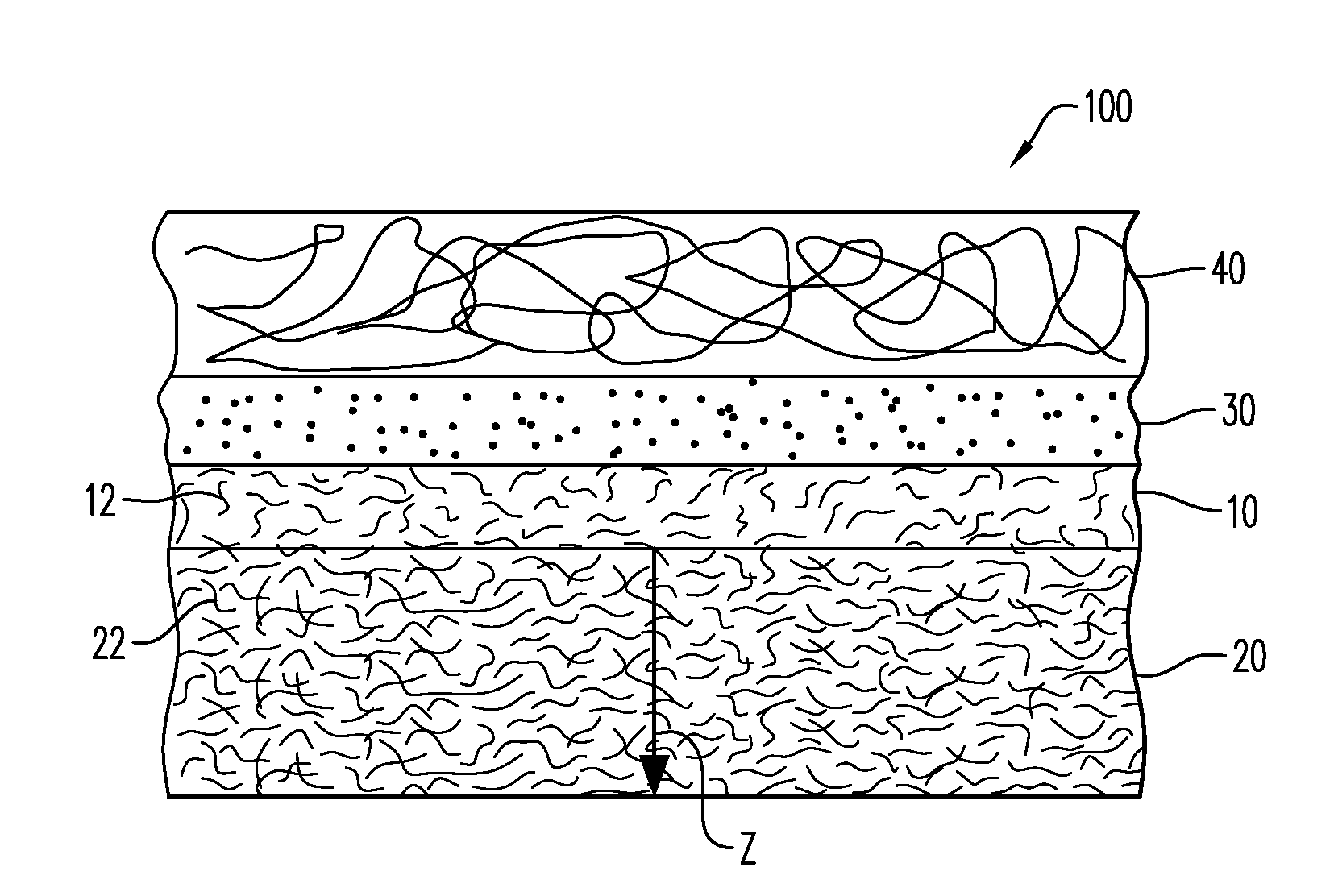
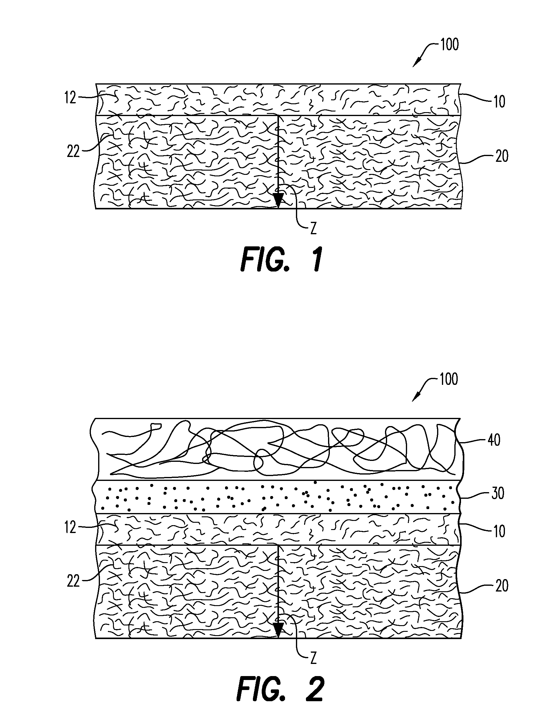
[0065]Samples of the composite filter medias 100 according to an embodiment were prepared in which a wet-laid nonwoven conductive layer 20 was made using 75 wt. % polyethylene terephthalate staple fibers of about 6.0 denier and / or 25.0 micron fiber diameter, and 12 to 24 mm lengths, 7.0+ wt. % carbon fibers of about 0.7 denier and / or 7.5 micron fiber diameter, and about 6.0 mm length, and 19 wt. % acrylic-styrene copolymer binder. The conductive layer 20 was made using an inclined wire wet laid process, as would be understood by one of ordinary skill in the art, and with a typical drying and curing oven to complete the forming system. The conductive layer 20 had a basis weight of 51 gsm, a thickness of about 0.007 inches, a stiffness of about 500 mg, an alpha of about −7 microsiemens. The nanofiber layer 10 was made from solution spun polystyrene fibers having a diameter of about 300 nm using the solution spun process described hereinabove and was formed directly onto the wet-laid n...


PUM

PropertyMeasurementUnit
Diameteraaaaaaaaaa
Volumetric flow rateaaaaaaaaaa
Electrical conductanceaaaaaaaaaa

Abstract

A composite filter media of a nanofiber layer that includes nanofibers formed from non-polar, non-conductive thermoplastic polymers using a solution spinning process to form the nanofibers directly onto a conductive layer is presented, along with the associated methodology for making such media. The conductive layer includes at least about greater than about 5 wt. % conductive fibers, Z-directional conductivity and a uniform surface conductivity of at least about 10−7 microsiemens.

Description

CROSS-REFERENCE TO RELATED APPLICATIONS[0001]This application claims benefit of U.S. Provisional Application No. 62 / 129,612 filed Mar. 6, 2015, which is incorporated herein by reference in its entirety.FIELD[0002]A composite filter media for removing particulates from a fluid is generally described. In particular, the composite filter media includes a nanofiber layer formed directly onto a conductive layer.BACKGROUND[0003]Webs of very fine fibers, that is, fibers having a diameter of less than about 1 micron (1000 nanometers), are well known in the art to make highly efficient air filtration media. One known method to form such “nanofibers” is to use an electrostatic discharging process on streams of polymer solutions, often referred to as electrospinning. While higher loadings of nanofibers tend to result in higher efficiency media, charges built up in the collected fiber web can result in limitations on how much fiber can be collected in this manner, thus limiting the range of pos...

Claims


Application Information

Patent Timeline
IPC IPC(8): B01D39/16D01D5/00
CPCD01D5/0007B01D39/1623B01D39/2065B01D2239/0241B01D2239/0258B01D2239/0435B01D2239/0631B01D2239/064B01D2239/0654B01D2239/1233B01D2239/1258B01D2239/1291
Inventor SANDERS, ROBERT G.GROSS, STEPHEN EDWARDLINTZ, TIMOTHY SCOTT
Owner LYDALL INC
Why Eureka
Try Eureka