Pressure controller for injection molding machine

a pressure controller and injection molding machine technology, applied in coatings and other directions, can solve the problems of increased cost, difficult to reduce the pressure in the mold to a desired pressure, and defective products, and achieve the effects of high response speed, reduced mold pressure variations in the molding cycle, and controlled mold pressur

Active Publication Date: 2016-09-08
FANUC LTD
View PDF5 Cites 10 Cited by
  • Summary
  • Abstract
  • Description
  • Claims
  • Application Information

AI Technical Summary

Benefits of technology

[0015]An object of the present invention is to provide a pressure controller for an injection molding machine capable of controlling an injection pressure after injection dwell switching to become a set pressure by an injection pressure control unit to reduce variations of pressure in a mold in molding cycles and to provide molded articles of stable quality. Another aspect of the invention is to provide a pressure controller for an injection molding machine capable of performing control such that an estimated in-mold pressure becomes a set in-mold pressure to control the pressure in the mold at a high response speed, and immediately reduce the pressure in the mold to prevent stress deformation of molded articles. Another aspect of the invention is to provide a pressure controller for an injection molding machine capable of controlling an injection pressure or an estimated in-mold pressure to control the pressure in the mold more accurately.
[0025]According to the aspects of the invention, the injection pressure after the injection dwell switching is controlled to become a set pressure by the injection pressure control unit, and thereby pressure variations in the mold in the molding cycles can be reduced. Consequently, molded article of stable quality can be provided.
[0026]Further, by controlling the estimated in-mold pressure to become a set in-mold pressure, the pressure in the mold can be controlled at a high response speed. Consequently, the pressure in the mold can be immediately reduced, and stress deformation of molded articles can be prevented.
[0027]Further, by controlling the injection pressure or the estimated in-mold pressure, the pressure in the mold can be more accurately controlled.

Problems solved by technology

If the high peak pressure is not reduced immediately, stress deformation may occur in the molded article, and may result in a defective product.
Consequently, it is difficult to reduce the pressure in the mold to a desired pressure at a desired response speed.
However, it is necessary to provide the additional pressure sensor in the mold, and this increases the cost.
However, all of the above techniques describe to simply move the screw backward by the position control for depressurization in the latter half of the filling step, and there is a problem that it is difficult to reduce the pressure in the mold at a desired response speed.
However, injecting the molten material in the mold-open state may damage the mold.
However, it is necessary to provide an additional pressure sensor in the mold, and this increases the cost.
Further, there is a possibility that the pressure control for controlling the resin pressure at the gate side to become the same pressure as the resin pressure at the opposite side of the gate is not always suitable for the thin-wall molding.
However, it is necessary to provide the additional pressure sensors in the mold, and this increases the cost.

Method used


Image

  • Pressure controller for injection molding machine
  • Pressure controller for injection molding machine
  • Pressure controller for injection molding machine

Examples


Embodiment Construction

[0037]Hereinafter, an embodiment of the present invention will be described with reference to the attached drawings.

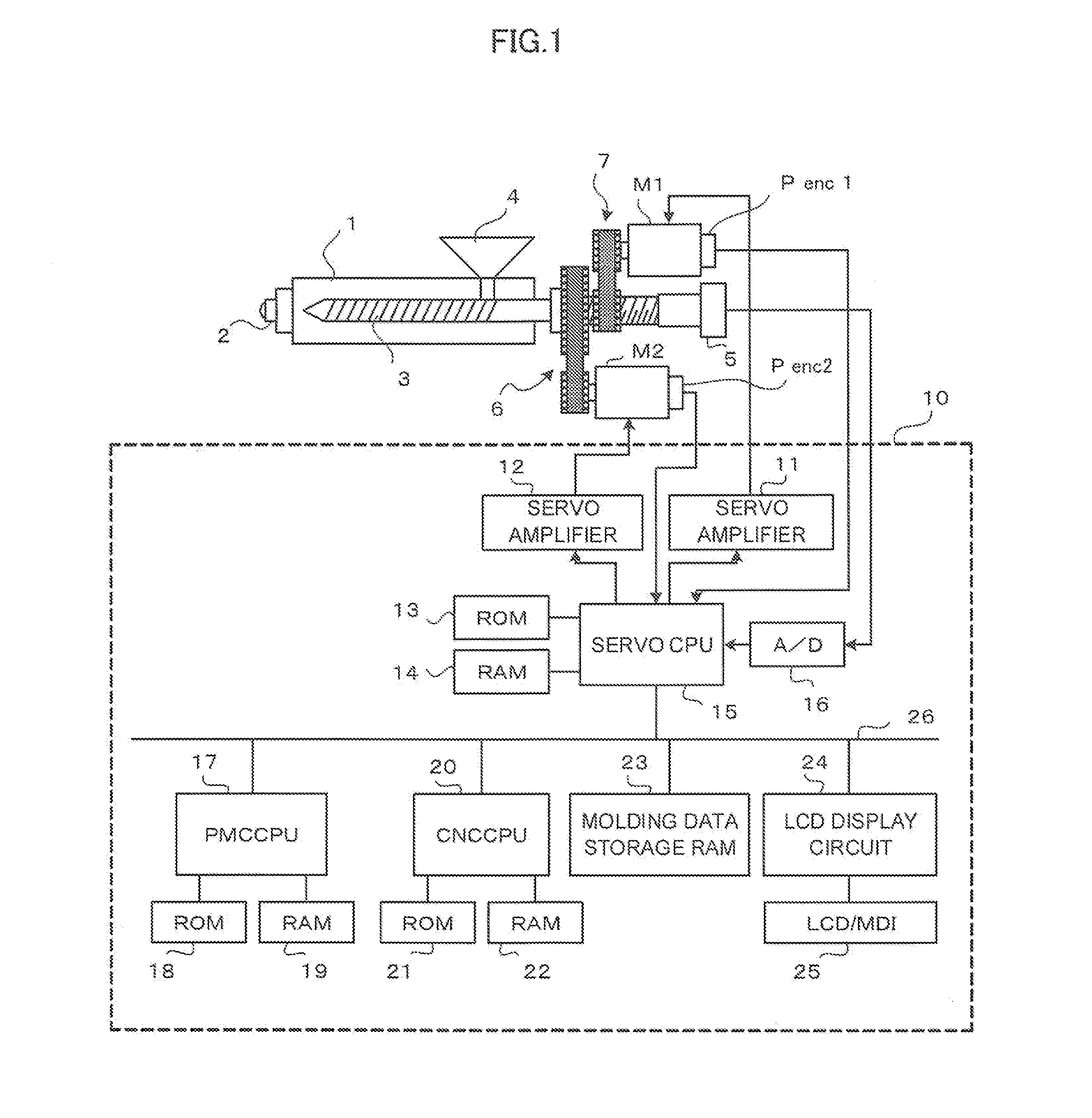
[0038]FIG. 1 is a schematic block diagram of an injection molding machine and a controller for controlling the injection molding machine. Into a cylinder 1, a screw 3 is inserted. To the tip of the cylinder 1, a nozzle 2 is attached, and on a side part in a rear end of the cylinder 1, a hopper 4 for supplying resin pellets to the cylinder 1 is attached. The screw 3 is driven in its axial direction to perform injection and back pressure control by an injection servomotor M1 that serves as a drive unit for driving the screw 3 in its axial direction, a power train, and a conversion mechanism 7 that converts rotary motion into rectilinear motion such as a ball screw and a nut. The screw 3 is also driven to rotate by a servomotor M2 that serves as a rotation drive unit for rotating the screw 3, and a power train 6 including a belt, a pulley, and the like.

[0039]To the inject...


PUM

PropertyMeasurementUnit
pressureaaaaaaaaaa
pressure detectionaaaaaaaaaa
in-mold pressureaaaaaaaaaa

Abstract

A pressure controller for an injection molding machine capable of reducing variations of pressure in a mold in molding cycles and providing molded articles of stable quality is provided. The pressure controller includes an in-mold pressure estimation unit for estimating a pressure in the mold based on an injection pressure detected with an injection pressure detection unit, and an amount of movement of a screw detected with a screw movement amount detection unit, and an in-mold pressure control unit for controlling such that the estimated in-mold pressure becomes a set in-mold pressure after the pressure control is performed in a dwell step with an injection pressure control unit.

Description

BACKGROUND OF THE INVENTION[0001]1. Field of the Invention[0002]The present invention relates to injection molding machines, and more particularly, to a pressure controller for an injection molding machine.[0003]2. Description of the Related Art[0004]An in-line screw injection molding machine performs a measurement step, an injection step, and a dwell step. In the measurement step, a screw in a heating cylinder is rotated while the screw is moved backward to press and send a molten resin to a tip portion of the heating cylinder, and then, in the injection step and the dwell step, the screw is moved forward to fill a mold with the molten resin.[0005]In the injection step, the screw is moved forward based on an injection stroke and an injection speed set in advance to fill the mold with the molten resin in the heating cylinder. When the screw is moved to an injection / dwell switching position, the injection step is switched to the dwell step. In the dwell step, pressure control is perf...

Claims


Application Information

Patent Timeline
Patent Type & Authority Applications(United States)
IPC IPC(8): B29C45/77B29C45/17B29C45/50B29C45/76B29C45/00
CPCB29C45/77B29C2045/776B29C45/0025B29C45/50B29C45/1774B29C2945/76006B29C2945/76096B29C2945/76595B29C2945/76498B29C2945/76381B29C2945/76859B29C2945/76862B29C2945/76969B29C2945/76187B29C2945/76665B29C45/768
Inventor MARUYAMA, JUNPEI
Owner FANUC LTD
Why Eureka
Try Eureka