Multilayer Floor Covering

Active Publication Date: 2016-09-08
GERFLOR
View PDF1 Cites 2 Cited by
  • Summary
  • Abstract
  • Description
  • Claims
  • Application Information

AI Technical Summary

Benefits of technology

[0017]reduce the surface density by r

Problems solved by technology

However, these reinforcing layers add considerable weight to the floor covering in particular because of the presence of reinforcement fibers, for example fiberglass.
Furthermore, the possible incompatibility of the resin used in these reinforcing layers with other product layers often requires the presence of intermediate adhesive layers or primer layers that provide an interface.
Not only can these additional layers make the mul

Method used


Image

  • Multilayer Floor Covering
  • Multilayer Floor Covering

Examples


Example

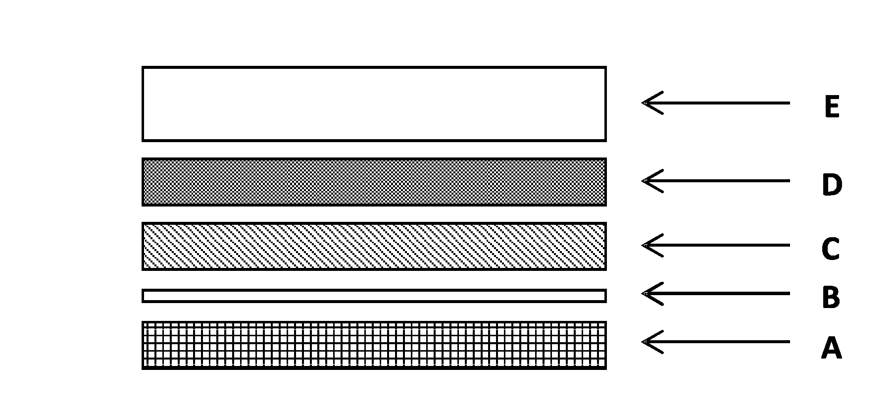
[0024]An embodiment of a multilayer floor covering includes a layer A of reinforcing fibers; an adhesive layer B; an underside layer C; a reinforcing layer D, free of reinforcing fibers, made of a thermoplastic polymer chosen from the group comprising polyester resins, acrylic resins and mixtures thereof; and a surface layer E.

[0025]Advantageously, in this multilayer, the reinforcing layer D has a thickness ranging from between 0.07 mm and 0.40 mm, and advantageously a surface density ranging from between 50 and 500 g / m2.

[0026]It involves a multilayer comprising a composite laminate (layer A of reinforcing fibers) and a polymeric surface complex (layers C, D and E).

[0027]Advantageously, the multilayer includes, successively, the layers A, B, C, D and E.

[0028]In general, a layer includes two main sides corresponding to an upper side and a lower side.

[0029]The reinforcing layer A corresponds to the lowest layer of the multilayer. It is intended to be in contact with the floor upon whi...


PUM

PropertyMeasurementUnit
Fractionaaaaaaaaaa
Fractionaaaaaaaaaa
Thicknessaaaaaaaaaa

Abstract

A multilayer floor covering includes a layer A of reinforcing fibers, an adhesive layer B, an underside layer C, a reinforcing layer D, free of reinforcing fibers, made of thermoplastic polymer chosen from the group comprising polyester resins, acrylic resins and mixtures thereof, and a surface layer E.

Description

CROSS-REFERENCE TO RELATED APPLICATIONS[0001]This application claims the benefit of priority under 35 U.S.C. §119 of French Patent Application No. 1551924, filed Mar. 6, 2015, the entire content of which is hereby incorporated herein by reference, in its entirety.TECHNOLOGICAL FIELD[0002]The present description relates to a multilayer intended to be used as a floor covering in particular in vehicles transporting people, for example in the aeronautics field.BACKGROUND OF THE DISCLOSURE[0003]In fields such as aeronautics, major companies are constantly looking for new materials that will reduce costs.[0004]As an example, it can involve the optimization of the operation of aircraft by developing and using new materials which have satisfactory physical properties while being lighter than conventional materials. A reduction in fuel consumption therefore results in a reduction in an aircraft's operating costs.[0005]Since this type of improvement may be directed towards any kind of part, s...

Claims


Application Information

Patent Timeline
IPC IPC(8): B64C1/18B32B27/36B32B27/40B32B27/18B32B27/08B32B7/12B32B27/30
CPCB64C1/18B32B7/12B32B27/36B32B27/304B32B27/306B32B2605/18B32B27/08B32B27/40B32B2255/00B32B2262/101B32B27/18B32B27/20B32B27/22B32B27/286B32B27/30B32B27/308B32B27/38B32B27/42B32B33/00B32B37/06B32B37/10B32B2307/546B32B2307/72B32B2262/0269B32B2262/065B32B2270/00B32B2262/106B32B2264/101B32B2264/104B32B2471/00B32B5/022B32B5/024B32B27/12B32B2260/021B32B2260/046B32B2307/4023B32B2605/003
Inventor CINAUSERO, NICOLASGILLOT, THOMAS
Owner GERFLOR
Why Eureka
Try Eureka