Catalyst device for exhaust gas purification and method for exhaust gas purification
- Summary
- Abstract
- Description
- Claims
- Application Information
AI Technical Summary
Benefits of technology
Problems solved by technology
Method used
Image
Examples
first embodiment
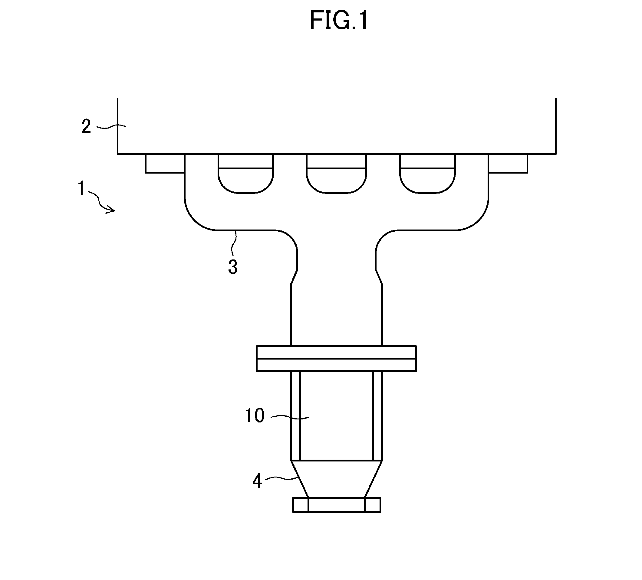
[0071]FIG. 1 shows a configuration of an exhaust gas purification catalytic device 1 as a first embodiment of the present invention. In FIG. 1, the reference number 2 denotes a cylinder head of a four-cylinder gasoline engine, the reference number 3 denotes an exhaust manifold connected to an exhaust port of the engine, the reference number 4 denotes an exhaust pipe connected to a downstream end of the exhaust manifold in the flowing direction of an exhaust gas, and the reference number 10 indicates a catalyst provided in the exhaust pipe. In this embodiment, the catalyst 10 is provided in the exhaust pipe 4. However, the catalyst 10 does not have to be provided there but may be provided in the exhaust manifold 3 instead.
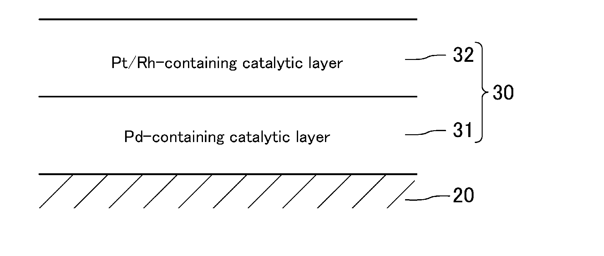
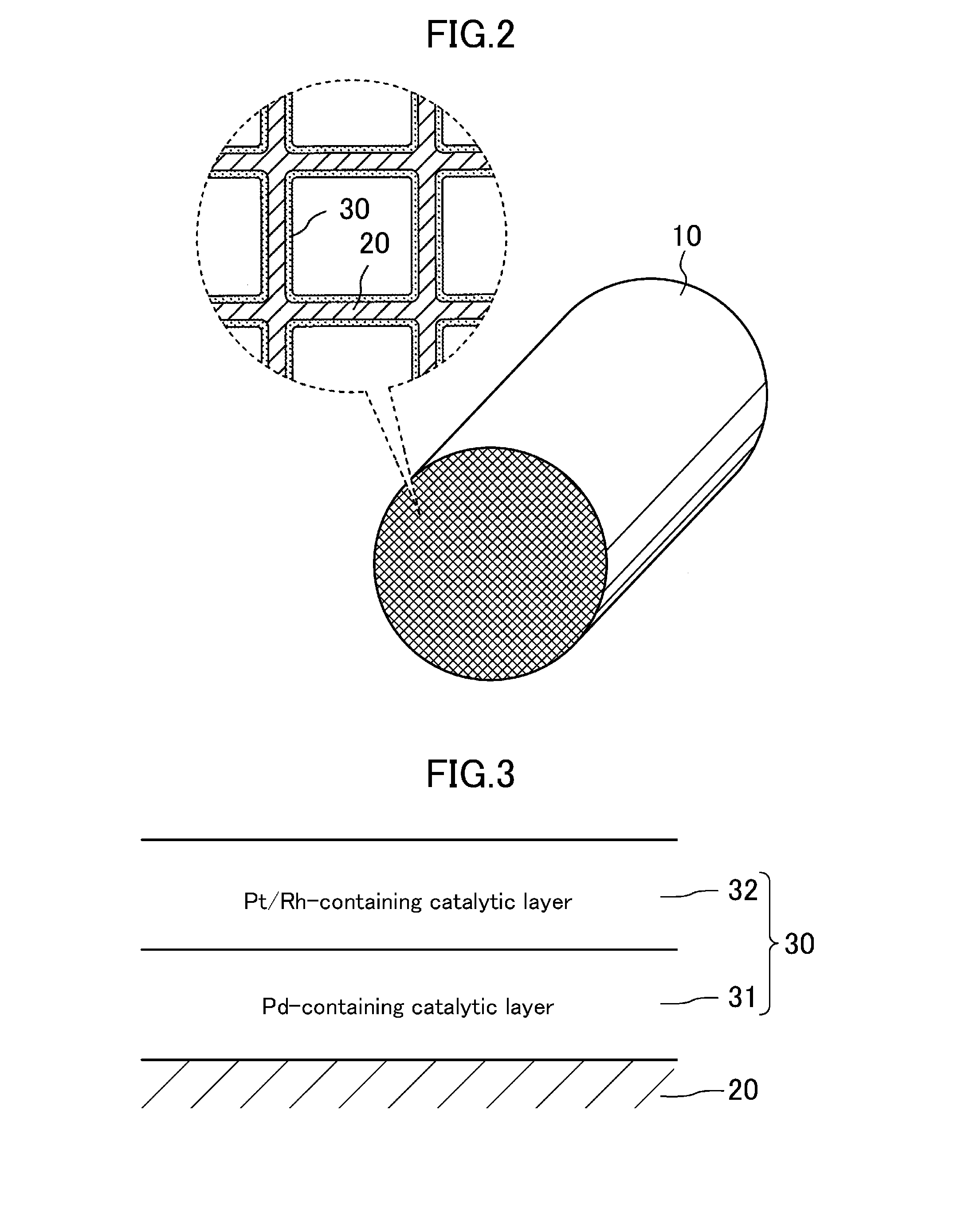
[0072]FIG. 2 shows a configuration for the catalyst 10. The catalyst 10 includes a stacked catalyst 30 disposed on the wall of an exhaust gas passage for a honeycomb substrate 20 made of cordierite.
[0073]
[0074]In this embodiment, the stacked catalyst 30 includes a p...
second embodiment
[0107]Next, an exhaust gas purification catalytic device according to a second embodiment of the present invention will be described. In the following description of this second embodiment, any members that are identical to the counterparts of the first embodiment described above will be identified by the same reference characters as their counterparts′, and will not be described in detail all over again. Instead, the following description will be focused on only the difference between this and that embodiments.
[0108]As shown in FIG. 8, the exhaust gas purification catalytic device 1 of the present embodiment includes a first catalyst 50 disposed at a collecting portion of an exhaust manifold 3 on a downstream side thereof in a flowing direction of an exhaust gas, and a second catalyst 60 is disposed in an exhaust pipe 4. That is to say, the first catalyst 50 is disposed upstream in the flowing direction of the exhaust gas, and the second catalyst 60 is disposed downstream of the fi...
examples
[0120]Some examples and comparative examples will be given below in order to describe the exhaust gas purification catalytic device of the present invention in detail. As for the examples, each including the uppermost catalytic layer containing the Pt-loaded silica-alumina that has already been described for the first embodiment, light-off temperatures (T50) indicative of purification of isopentane (C5H12) were measured, and the results of measurements were compared with those of comparative examples in each of which the uppermost catalytic layer did not contain the Pt-loaded silica-alumina.
[0121]In Examples 1-4, the same honeycomb substrates as the ones used in the measurement of the C5H12 purification rate shown in FIG. 7 were adopted. A stacked catalyst with a double-layer structure was provided on the substrate in each of Examples 1 and 2, while a stacked catalyst with a triple-layer structure was provided on the substrate in each of Examples 3 and 4. The following Table 3 shows...
PUM
| Property | Measurement | Unit |
|---|---|---|
| Temperature | aaaaa | aaaaa |
| Content | aaaaa | aaaaa |
| Thermal properties | aaaaa | aaaaa |
Abstract
Description
Claims
Application Information
 - R&D
- Intellectual Property
- Life Sciences
- Materials
- Tech Scout
- Unparalleled Data Quality
- Higher Quality Content
- 60% Fewer Hallucinations
Browse by: Latest US Patents, China's latest patents, Technical Efficacy Thesaurus, Application Domain, Technology Topic, Popular Technical Reports.
© 2025 PatSnap. All rights reserved.Legal|Privacy policy|Modern Slavery Act Transparency Statement|Sitemap|About US| Contact US: help@patsnap.com


