Hybrid vehicle

a hybrid vehicle and battery technology, applied in the direction of engine-driven generators, battery/fuel cell control arrangements, transportation and packaging, etc., can solve the problem of lower charging cost of the battery by the engine output than by external charging, and achieve the effect of reducing travel costs, increasing electric storage devices, and reducing charging costs of hybrid vehicles

Active Publication Date: 2016-09-15
TOYOTA JIDOSHA KK
View PDF3 Cites 67 Cited by
  • Summary
  • Abstract
  • Description
  • Claims
  • Application Information

AI Technical Summary

Benefits of technology

[0010]The present specification discloses a configuration that reduces a total travel cost in a hybrid vehicle in which an on-board electrical storage device can be charged by a power supply on the outside of the vehicle.
[0012]According to the above hybrid vehicle, an SOC value of the electrical storage device is increased by executing the electrical storage amount recovery control, by which charging efficiency of the electrical storage device can be increased, during traveling on the freeway, and the EV travel is made on the open road by using the electric power stored in the electrical storage device. In this way, compared to a case where the hybrid vehicle travels on the open road while an SOC is maintained in a specified level, a travel cost can be reduced. Furthermore, the target value in the charging amount recovery control that is executed during traveling on the freeway is set on the basis of the comparison result between the first travel cost and the second travel cost. In this way, charging cost of the hybrid vehicle can be reduced. As a result, a total travel cost of the hybrid vehicle can be reduced.
[0014]When it is configured as described above, in the case where the first travel cost is higher than the second travel cost, the SOC of the electrical storage device at the destination is recovered to a full charge state by external charging. In this way, the charging cost of the electrical storage device can be reduced. Thus, the total travel cost of the hybrid vehicle can be reduced.
[0016]When it is configured as described above, in the case where the first travel cost is lower than the second travel cost, a larger electric power amount than an electric power amount required for the travel on the open road is stored in the electrical storage device. In this way, an electric power amount that is charged by the external charging at the destination can be reduced. In this way, the charging cost can be reduced. Thus, the total travel cost of the hybrid vehicle can be reduced.
[0018]When it is configured as described above, the charging amount recovery control is executed when the engine is operated at the engine operation point at which the charging efficiency of the electrical storage device is increased in the case where the first travel cost is equal to the second travel cost. As a result, the travel cost at a time when the EV travel is made by using the electric power that is charged on the freeway can be reduced. In this way, the total travel cost of the hybrid vehicle can be reduced.
[0020]When it is configured as described above, the SOC value of the electrical storage device is increased by executing the electrical storage amount recovery control during selection of the parallel HV travel in which the charging efficiency of the electrical storage device can be increased, and the EV travel is made on the open road by using the electric power stored in the electrical storage device. In this way, the travel cost can be reduced. Furthermore, the target value in the charging amount recovery control that is executed during selection of the parallel HV travel is set on the basis of a comparison result between the first travel cost and the second travel cost. In this way, the charging cost of the hybrid vehicle can be reduced. As a result, the total travel cost of the hybrid vehicle can be reduced.

Problems solved by technology

In such a case, there is a possibility that charging cost of the battery by the engine output is lower than charging cost thereof by external charging.

Method used


Image

  • Hybrid vehicle
  • Hybrid vehicle
  • Hybrid vehicle

Examples


first embodiment

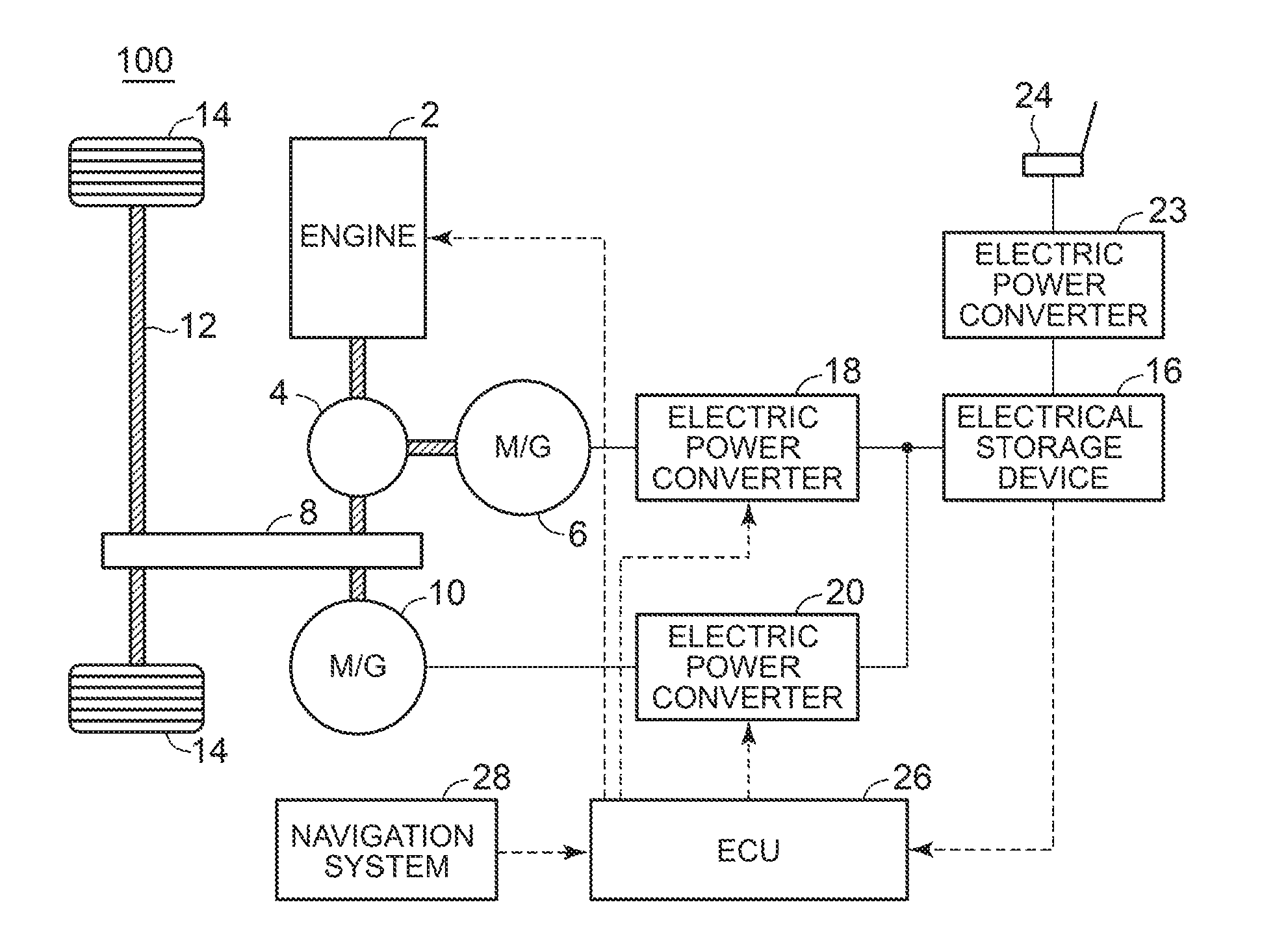
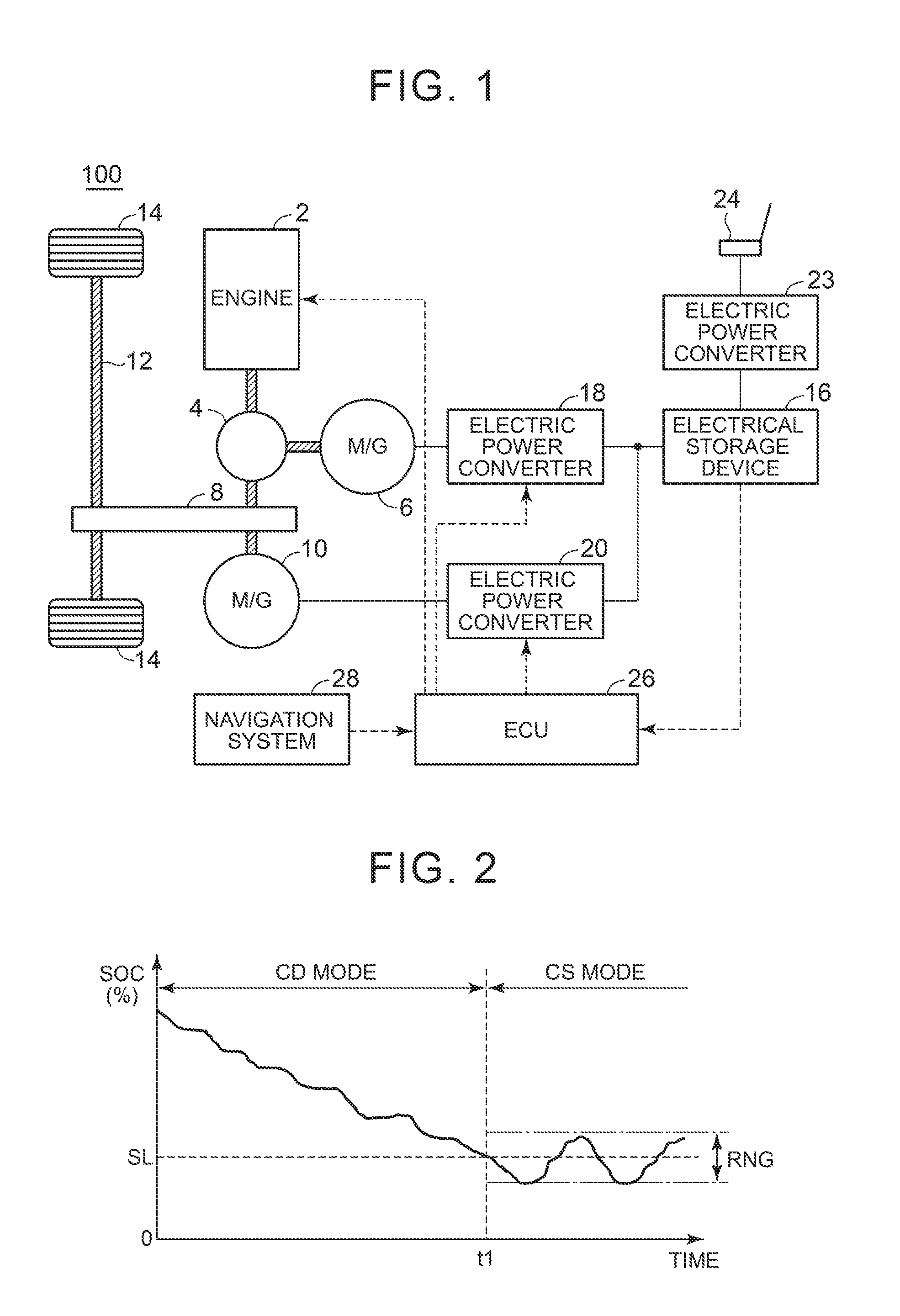
[0043]FIG. 1 is a block diagram for explaining an overall configuration of a hybrid vehicle according to a

[0044]With reference to FIG. 1, a hybrid vehicle 100 includes an engine 2, a power split device 4, motor generators 6, 10, a transmission gear 8, a drive shaft 12, and drive wheels 14. The hybrid vehicle 100 further includes an electrical storage device 16, electric power converters 18, 20, 23, a connection section 24, and an electronic control unit (ECU) 26.

[0045]The engine 2 is an internal combustion engine that outputs power by converting thermal energy produced from combustion of fuel into kinetic energy of motion elements such as a piston and a rotor. In some embodiments, the fuel of the engine 2 is hydrocarbon fuel such as gasoline, diesel gasoline, ethanol, liquid hydrogen, and natural gas or hydrogen fuel in liquid or gas.

[0046]The motor generators 6, 10 are each an AC rotary electric machine and, for example, constructed of a three-phase AC synchronous electric motor. T...

second embodiment

[0160]That is, the disclosed subject matter can be applied commonly to a hybrid vehicle that has a vehicle configuration capable of increasing the electrical storage amount (the SOC) of the electrical storage device by engine output. In the second embodiment, as shown in FIG. 14, the disclosed subject matter is applied to a hybrid vehicle 100A that is configured by mechanically coupling the engine 2 and the drive wheels 14 via a clutch 30.

[0161]FIG. 14 is a block diagram that shows an overall configuration of the hybrid vehicle according to the second embodiment.

[0162]With reference to FIG. 14, the hybrid vehicle 100A includes the engine 2, the motor generators 6, 10, the clutch 30, the drive wheels 14, gears 31, 32, an output gear 34, a differential gear device 36, the drive shaft 12, an electric power converter unit (PCU) 22, the electrical storage device 16, and an ECU 26A. In addition, the hybrid vehicle 100A further includes the electric power converter 23 and the connection se...


PUM


Abstract

The electronic control unit sets a target value of a charging amount of the electrical storage device and increases the charging amount to the target value during traveling on the freeway. The electronic control unit computes a first travel cost being cost per unit travel distance of fuel used when the EV travel is made by using the electric power charged in the electrical storage device at a time when the HV travel is made on the freeway, and the second travel cost being cost per unit travel distance of the electric power used when the EV travel is made by using the electric power charged in the electrical storage device by the charging mechanism at the destination. The electronic control unit sets the target value on the basis of a comparison result between the first travel cost and the second travel cost.

Description

CROSS-REFERENCE TO RELATED APPLICATIONS[0001]This application claims priority to Japanese Patent Application No. 2015-045673 filed on Mar. 9, 2015, the entire contents of which are hereby incorporated by reference.BACKGROUND[0002]1. Field[0003]The disclosure relates to a hybrid vehicle in which an on-board electrical storage device can be charged by a power supply on the outside of the vehicle.[0004]2. Description of Related Art[0005]Japanese Patent Application Publication No. 2011-915 (JP 2011-915 A) discloses a hybrid vehicle that includes: an engine that generates power by using fuel; a battery that can be charged externally; and a motor generator that generates power by using electric power supplied from said battery. This hybrid vehicle is configured to control a drive ratio between the engine and the motor generator with respect to requested drive power such that the drive ratio of either the engine or the motor generator that can produce a higher economic effect is increased ...

Claims


Application Information

Patent Timeline
Patent Type & Authority Applications(United States)
IPC IPC(8): B60W20/13B60W10/08B60K6/442B60W10/06B60L50/15B60L50/16
CPCB60W20/13B60W10/06B60W10/08B60Y2300/91Y10S903/93B60Y2200/92B60Y2300/182B60K6/442B60L58/12B60W20/20B60W2510/242B60W2510/244B60W2530/00B60K6/445B60W20/12B60W50/0097B60W2552/05B60W2556/50B60W2710/244Y02T10/62Y02T10/70B60Y2300/92
Inventor HOTTA, MAKOTO
Owner TOYOTA JIDOSHA KK
Why Eureka
Try Eureka