

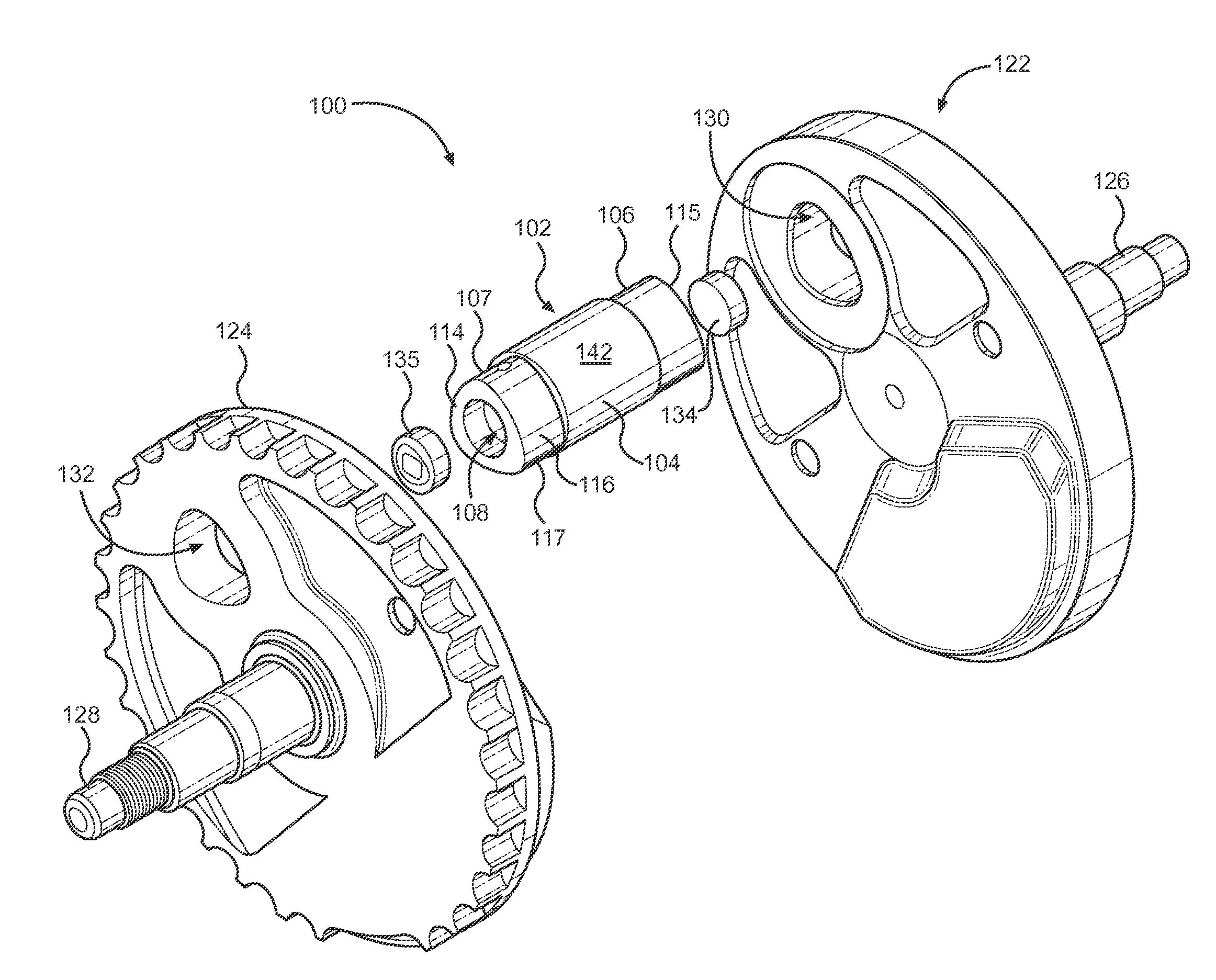
Crankshaft assembly with polygon crank pin
a crank pin and crankshaft technology, applied in the direction of connecting rod bearings, machines/engines, cycles, etc., can solve the problems of crankshaft assembly breakage, loss of the required perfect alignment of both flanges with each other, and more vibration, so as to increase strength and resistance to torque
- Summary
- Abstract
- Description
- Claims
- Application Information
AI Technical Summary
Benefits of technology
Problems solved by technology
Method used
Image

Examples
Embodiment Construction
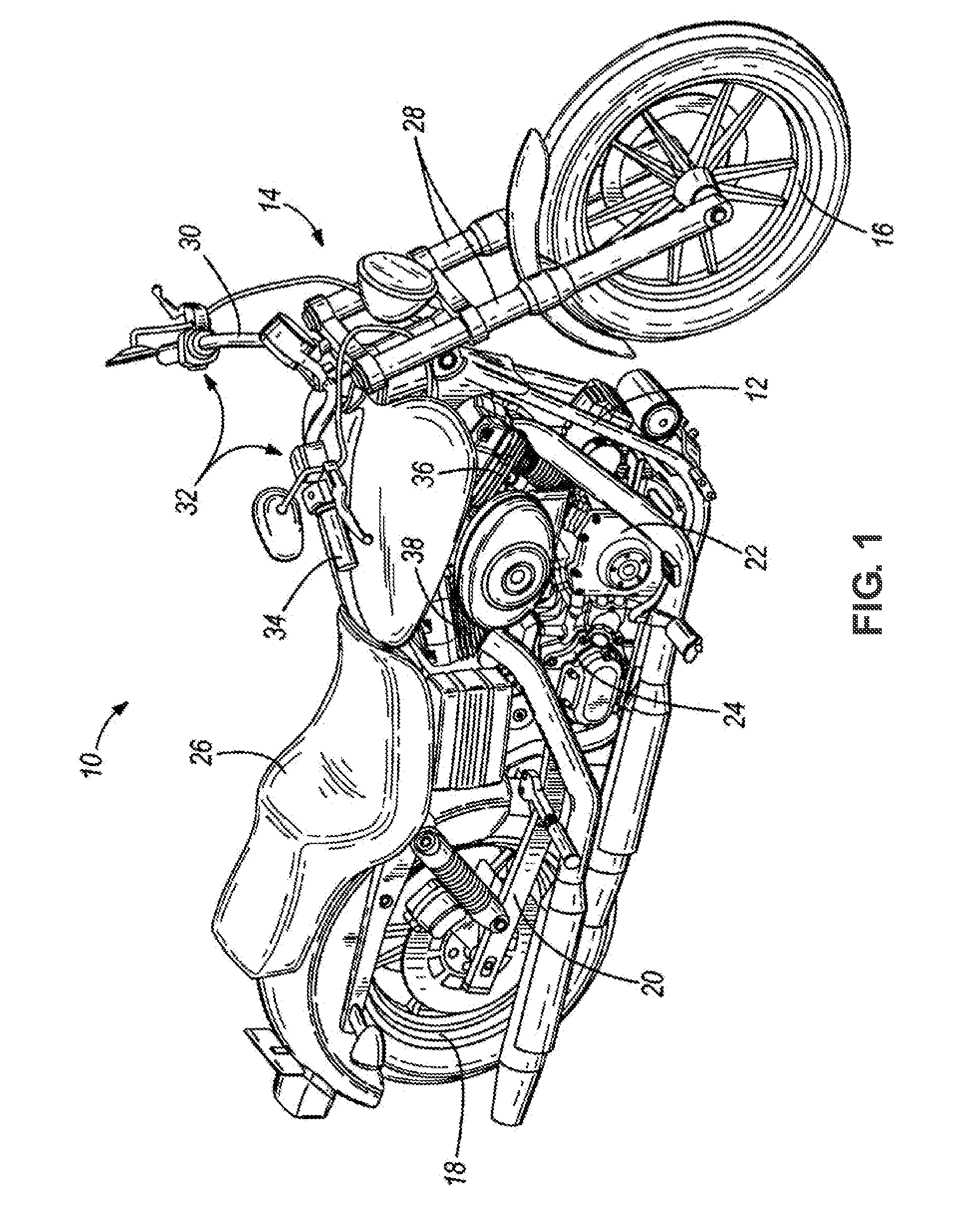
[0017]With initial reference to FIG. 1, an existing motorcycle 10 for use with the present invention is depicted. Motorcycle 10 includes a frame 12, a steering assembly 14 pivotably mounted to a forward portion of frame 12, a front wheel 16 rotatably mounted to an end of steering assembly 14, a rear wheel 18 rotatably mounted to a swing arm 20 that is pivotably connected to a rearward portion of frame 12, and an engine 22 and transmission 24 mounted to frame 12 and operably coupled to rear wheel 18. A seat 26 is coupled to frame 12 above rear wheel 18. The steering assembly 14 includes a fork 28, handlebars 30, and controls 32, such as a throttle grip 34, coupled to handlebars 30. As is well understood by one of ordinary skill in the art, an operator manipulates controls 32 to power engine 22 and transmission 24, drive rear wheel 18, and propel motorcycle 10. Handlebars 30 are manipulated to pivot steering assembly 14 and front wheel 16 to steer motorcycle 10. Engine 22 is an intern...
PUM
 Abstract
Description
Claims
Application Information