Endoscope device

a technology of endoscope and endoscope, which is applied in the direction of optical elements, instruments, applications, etc., can solve the problems that the noise component may not be appropriately reduced in the other imaging system, so as to achieve the effect of reducing a noise componen

Active Publication Date: 2016-09-29
OLYMPUS CORP
View PDF2 Cites 6 Cited by
  • Summary
  • Abstract
  • Description
  • Claims
  • Application Information

AI Technical Summary

Benefits of technology

[0010]According to one aspect of the present disclosure, there is provided an endoscope device according to the present disclosure includes: a light source unit configured to emit white illumination light including light of red, green and blue wavelength bands or narrow band illumination light formed of narrow band light included in each of the blue and green wavelength bands; an imaging device configured to perform photoelectric conversion on light received by a plurality of pixels arranged in a lattice pattern to generate an electric signal as an image signal; a color filter in which a filter unit is arranged so as to correspond to the plurality of pixels, the filter unit formed of a plurality of filters including at least a filter which transmits the light of the blue wavelength band and a filter which transmits the light of the blue wavelength band and the light of at least one of the green and red wavelength bands in which the number of filters which transmit the light of the green wavelength band is equal to or larger than half the total number of filters of the filter unit and the number of filters which transmit the light of the blue wavelength band is equal to or larger than the number of filters which transmit the light of the green wavelength band; and a noise reducing unit configured to select a pixel of interest based on used filter information determined according to the light emitted by the light source unit and a characteristic of each filter forming the color filter and detect motion between images captured at different times by using the electric signal output by the pixel of interest, thereby reducing a noise component included in the image signal.

Problems solved by technology

However, when the above-described white illumination light imaging system and narrow band imaging system are performed, when the NR processing is performed based on the pixel value output from the pixel on which a specific filter is provided, the pixel value of each pixel differs depending on different characteristics of the imaging system, so that there is a problem that the noise component may be appropriately reduced in one imaging system but the noise component may not be appropriately reduced in the other imaging system.

Method used


Image

  • Endoscope device
  • Endoscope device
  • Endoscope device

Examples


Embodiment Construction

[0027]A mode for carrying out the present disclosure (hereinafter, referred to as an “embodiment”) is hereinafter described. A medical endoscope device which captures an image in a body cavity of a subject such as a patient to display is described in the embodiment. The present disclosure is not limited by the embodiment. In the drawings, the same part is described with the same reference numeral assigned.

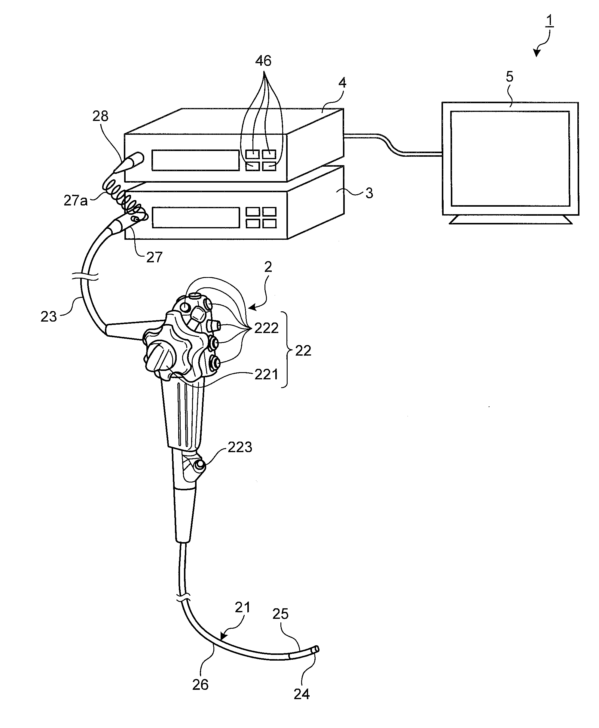
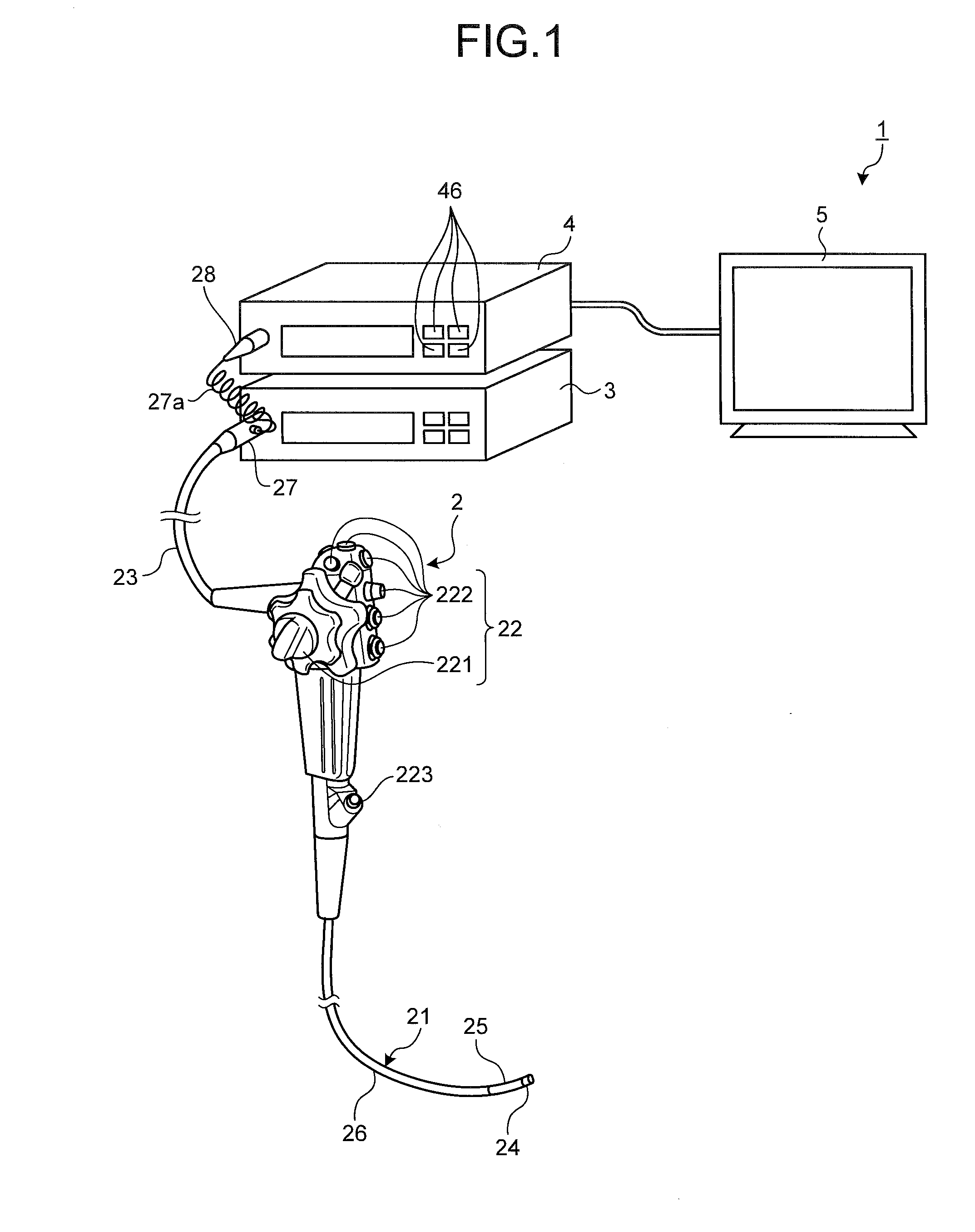
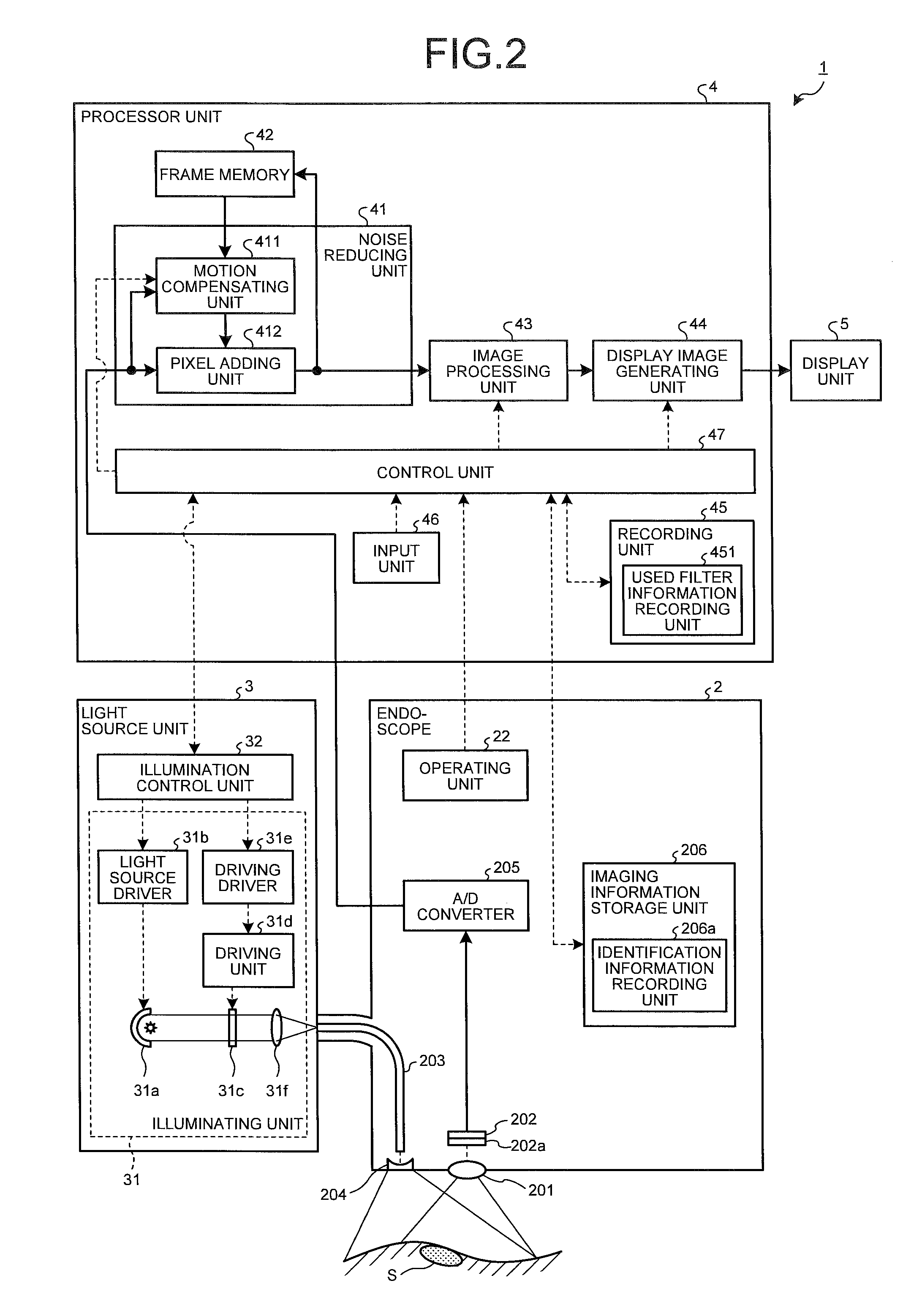
[0028]FIG. 1 is a view illustrating a schematic configuration of the endoscope device according to one embodiment of the present disclosure. FIG. 2 is a schematic diagram illustrating the schematic configuration of the endoscope device according to one embodiment of the present disclosure.

[0029]An endoscope device 1 illustrated in FIGS. 1 and 2 is provided with an endoscope 2 (endoscope) which image an observed region in the subject with a distal end inserted in the body cavity of the subject, thereby generating an in-vivo image (image signal) of the observed region, a light source...


PUM


Abstract

An endoscope device includes: a light source unit; an imaging device; a color filter in which a filter unit is arranged, the filter unit in which the number of filters which transmit light of a green wavelength band is equal to or larger than half the total number of filters and the number of filters which transmit light of a blue wavelength band is equal to or larger than the number of filters which transmit the light of the green wavelength band; and a noise reducing unit configured to select a pixel of interest based on used filter information determined according to the light emitted by the light source unit and a characteristic of each filter forming the color filter and detect motion between images captured at different times by using an electric signal output by the pixel of interest, thereby reducing a noise component included in the image signal.

Description

CROSS-REFERENCE TO RELATED APPLICATIONS[0001]This application is a continuation of PCT international application Ser. No. PCT / JP2014 / 074641 filed on Sep. 18, 2014 which designates the United States, incorporated herein by reference, and which claims the benefit of priority from Japanese Patent Applications No. 2013-264121, filed on Dec. 20, 2013, incorporated herein by reference.BACKGROUND[0002]1. Field of the Disclosure[0003]The present disclosure relates to an endoscope device introduced into a living body to obtain an in-vivo image.[0004]2. Description of the Related Art[0005]Technology of detecting a motion amount between frames based on a current frame and a previous frame corresponding to image signals temporally adjacent to each other generated by an imaging device to reduce a noise component of the current frame according to the motion amount is conventionally known as noise reduction processing (hereinafter, referred to as “NR processing)) of reducing the noise component in...

Claims


Application Information

Patent Timeline
Patent Type & Authority Applications(United States)
IPC IPC(8): A61B1/00A61B1/05A61B1/005A61B1/06
CPCA61B1/00009A61B1/0638A61B1/00114A61B1/0646A61B1/005A61B1/05A61B1/00186G06T3/4015H04N2209/046H04N2209/043G02B23/2484A61B1/000095H04N23/81H04N23/555H04N25/133H04N23/843H04N25/134
Inventor KURIYAMA, NAOYA
Owner OLYMPUS CORP
Why Eureka
Try Eureka