
Biophotonic measurement apparatus and biophotonic measurement method using same

a biophotonic measurement and apparatus technology, applied in the field of biophotonic measurement apparatus and biophotonic measurement method using same, can solve the problems of difficult methods, difficult to determine various coefficients in calculations, and difficult to assume optical path length of subjects, etc., to achieve efficient and sound data acquisition

Inactive Publication Date: 2016-09-29
HITACHI LTD
View PDF3 Cites 2 Cited by
  • Summary
  • Abstract
  • Description
  • Claims
  • Application Information

AI Technical Summary

Benefits of technology

The present invention allows for measuring brain and skin blood flow in real time, which helps to improve accuracy and efficiency in data acquisition. This invention can help to interrupt and redo the measurement if brain blood flow cannot be measured accurately.

Problems solved by technology

In this method, a configuration of the head is assumed as a two-layered model and a partial mean optical path length in each of the layers is further required to be assumed; however, assuming an optical path length of a subject is difficult.
These methods, however, have problems as described below.
Firstly, there is a problem that it is difficult to determine various coefficients in calculations such as subtraction among measurement signals of respective SD distances.
Therefore, an amplitude ratio of brain blood flow-derived components and skin blood flow-derived components is unknown and thus determining an appropriate coefficient for the calculation is difficult.
Furthermore, fitting short SD signals to long SD signals may disadvantageously remove brain blood flow-derived signals from the long SD signals when skin blood flow-derived signals and brain blood flow-derived signals are not independent, that is, the skin blood flow-derived signals and brain blood flow-derived signals are correlated.
Thus, processing to separate skin blood flow-derived signals and brain blood flow-derived signals is performed after measurement and no result can be obtained during measurement.

Method used


Image

  • Biophotonic measurement apparatus and biophotonic measurement method using same
  • Biophotonic measurement apparatus and biophotonic measurement method using same
  • Biophotonic measurement apparatus and biophotonic measurement method using same

Examples


example 1

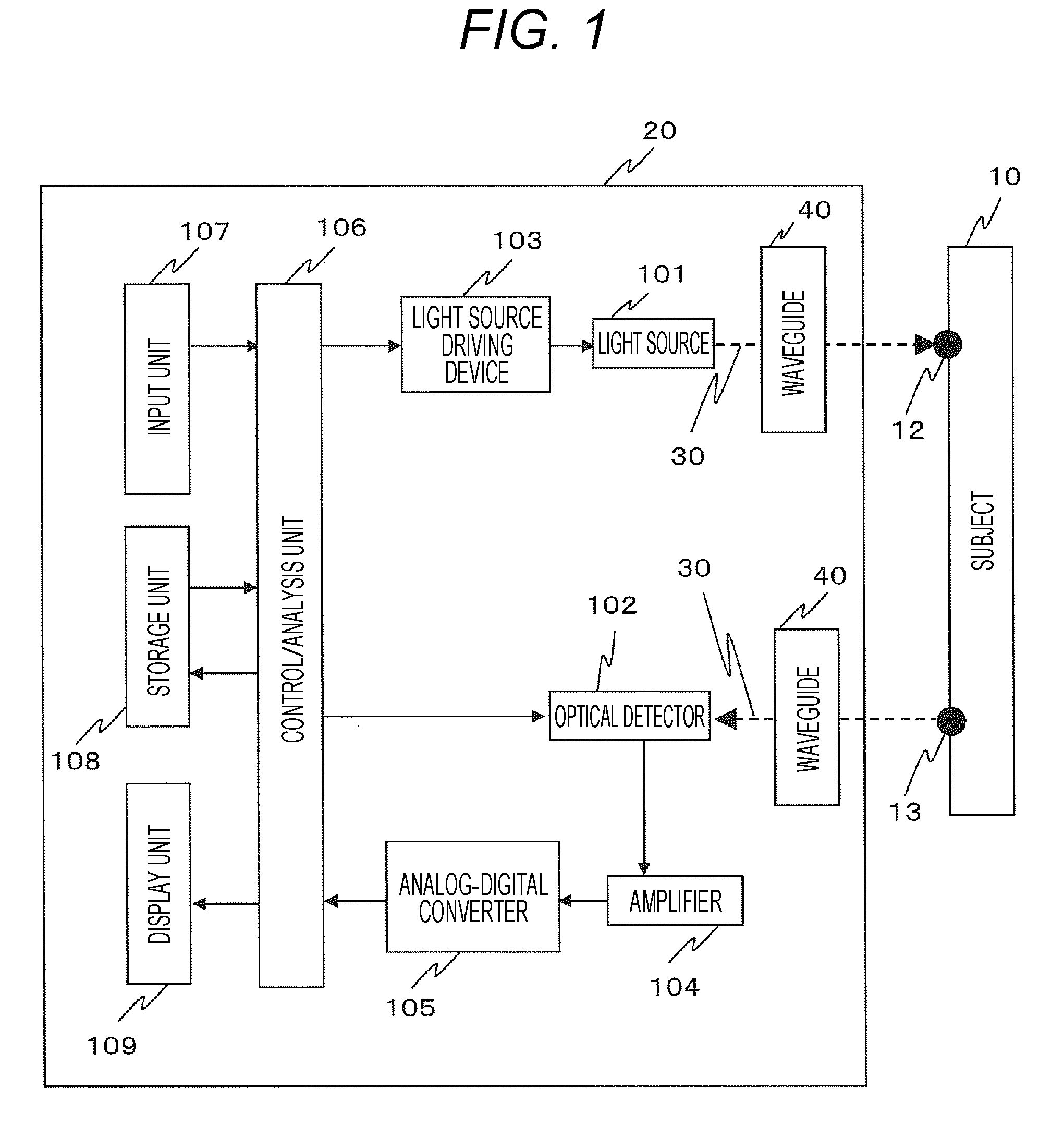
[0035]An exemplary configuration of an apparatus of the present invention is illustrated in FIG. 1. With a biophotonic measurement apparatus capable of emitting light to a living body and detecting light output from the living body after diffusion, absorption, and propagation therein, light 30 irradiated from one or more light sources 101 included in an apparatus main body 20 enters a subject 10 via a waveguide 40. The light 30 enters inside the subject 10 from an irradiation point 12, is transmitted and propagated within the subject 10, and then detected by one or more optical detectors 102 via a waveguide 40 from a detection point 13 located away from the irradiation point 12. An SD distance is defined by, as described above, a distance between the irradiation point 12 and detection point 13.

[0036]Here, the one or more light sources 101 are only required to be semiconductor lasers (LDs), light-emitting diodes (LEDs), or the like and the one or more optical detectors are only requi...


PUM


Abstract

Signals derived from the brain or cerebral cortex are extracted by separating and removing influence of the skin blood flow included in NIRS signals. Provided is a biophotonic measurement apparatus to separate signals simultaneously measured with a plurality of irradiator-detector distances (SD distances) into brain blood flow-derived signals and skin blood flow-derived signals using SD distance dependency of signal amplitudes.

Description

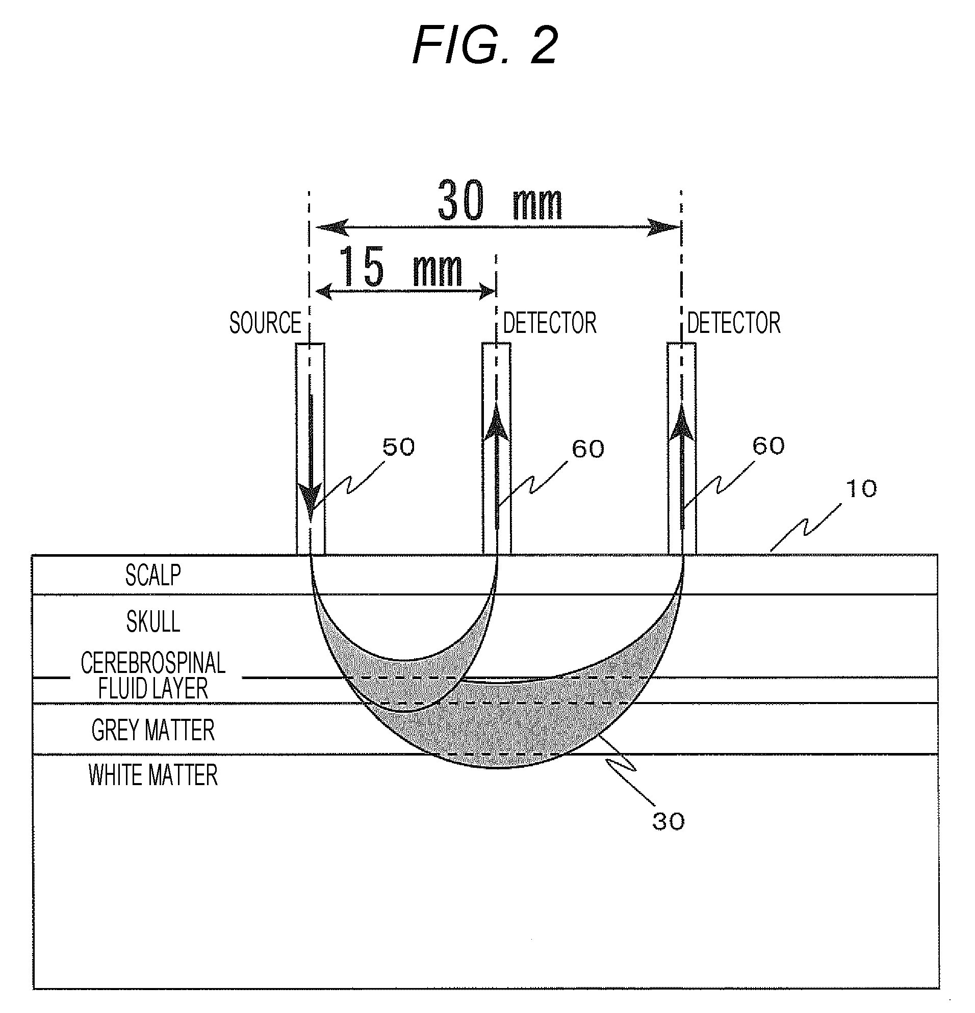
TECHNICAL FIELD[0001]The present invention relates to a technique to separate and remove influence of surface layer components such as skin blood flow components mixed in signal components using a biophotonic measurement apparatus using visible light or near infrared light.BACKGROUND ART[0002]It is reported that optical detection signals and biological signals (hereinafter referred to as NIRS signals) obtained from non-invasive optical brain function imaging using NIRS including optical topography may be affected by variations in skin blood flow in the scalp since irradiation with light is performed on / over the scalp. In consideration of such influence of skin blood flow, methods to extract and remove components thereof are studied. Most of such methods acquire signal components from portions with different depths by method using a plurality of irradiator-detector (source-detector) distances (hereinafter referred to as SD distance) and intend to remove, using the signal components, ...

Claims


Application Information

Patent Timeline
Patent Type & Authority Applications(United States)
IPC IPC(8): A61B5/026A61B5/00
CPCA61B5/0261A61B5/7425A61B2562/0238A61B5/7203A61B5/4064A61B5/746A61B5/0075A61B5/14552A61B5/7214
Inventor KIGUCHI, MASASHIFUNANE, TSUKASA
Owner HITACHI LTD
Learn More