Engine lubricating device

Active Publication Date: 2016-09-29
KUBOTA LTD
View PDF2 Cites 4 Cited by
  • Summary
  • Abstract
  • Description
  • Claims
  • Application Information

AI Technical Summary

Benefits of technology

[0018]<<Effect 3>> Inclination performance of an engine is high.
[0019]Even if an opening area of the strainer inlet is small, it is possible to secure a large enough necessary filtration area at the filter portion. Even whe

Problems solved by technology

As a result, a horsepower loss d

Method used


Image

  • Engine lubricating device
  • Engine lubricating device
  • Engine lubricating device

Examples


Embodiment Construction

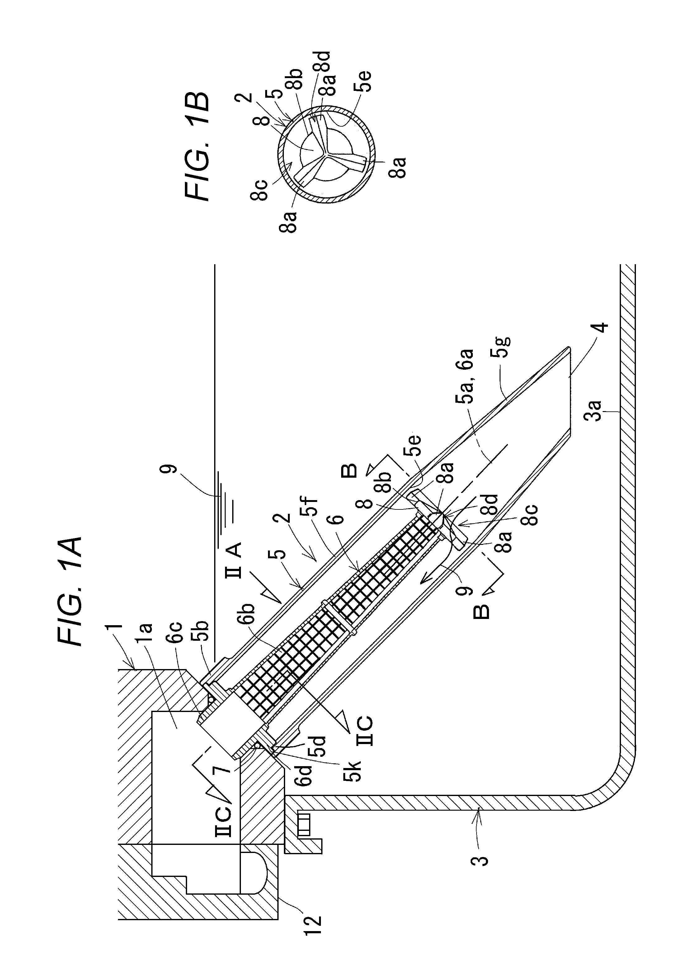
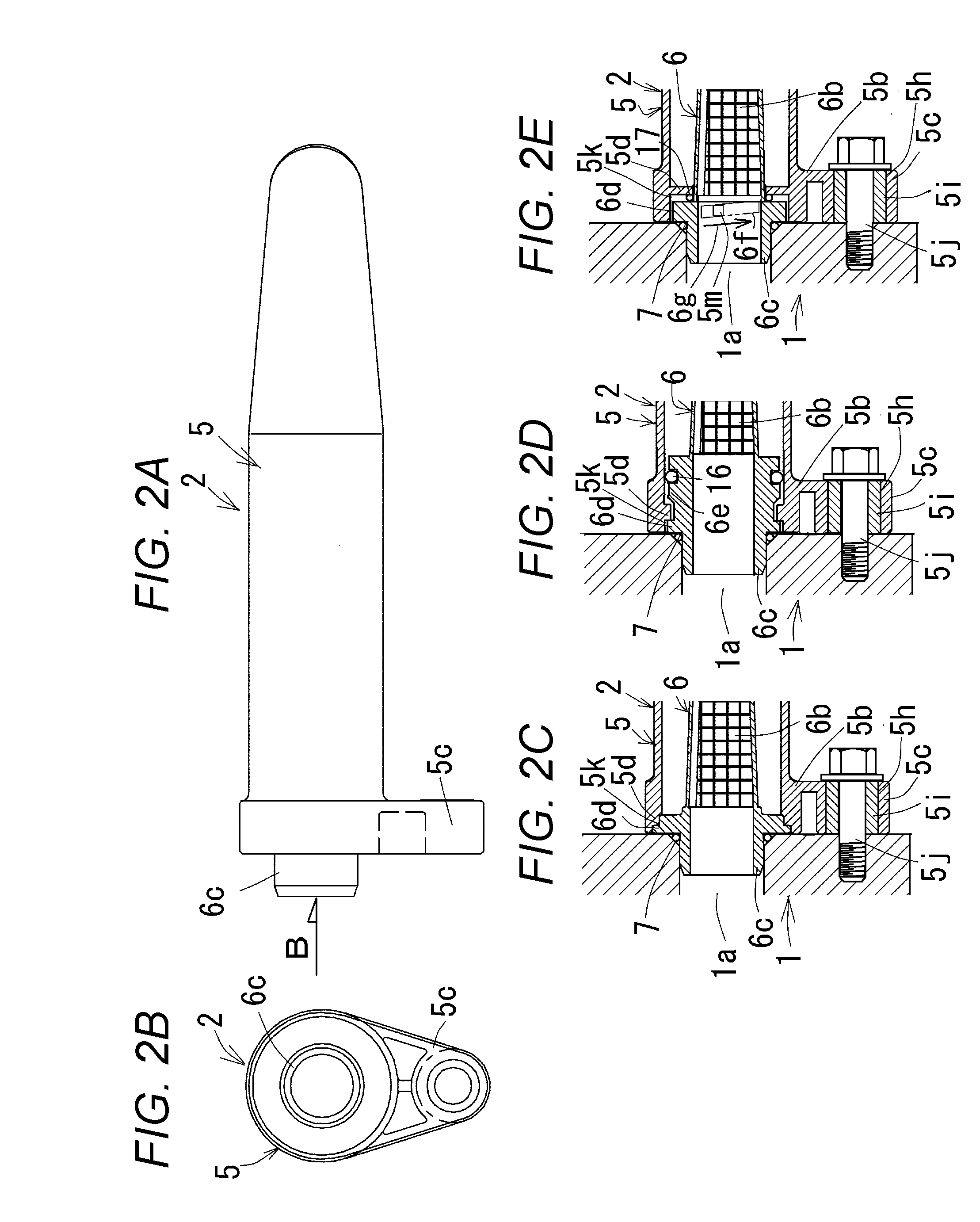
[0024]FIGS. 1A to 4 are drawings for explaining an engine lubricating device according to an embodiment of the present invention. In the embodiment, a vertical straight two-cylinder diesel engine will be described.

[0025]A general outline of the engine is as follows.

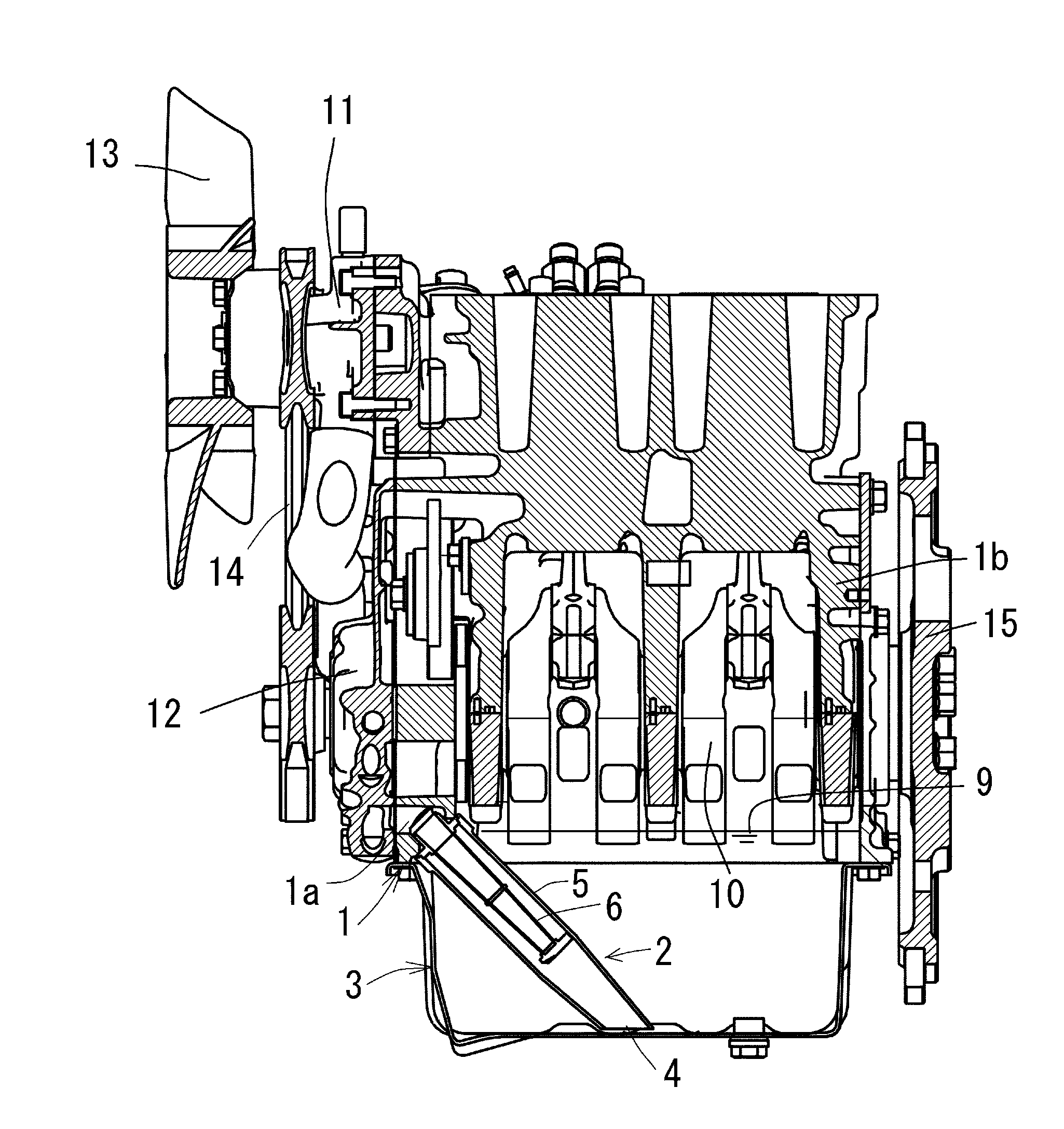
[0026]As shown in FIG. 4, a cylinder head (not shown) is mounted to an upper portion of a cylinder block (1) and a cylinder head cover (not shown) is mounted to an upper portion of the cylinder head. In a crankcase (1b) of the cylinder block (1), a crankshaft (10) is supported. A water pump (11) and an oil pump (12) are mounted to a front portion of the cylinder block (1), an engine cooling fan (13) is disposed in front of the water pump (11), the water pump (11) and the engine cooling fan (13) are driven by the crankshaft (10) via a fan belt (14), and the oil pump (12) is also driven by the crankshaft (10).

[0027]The cylinder block (1) has an oil passage inlet (1a) communicating with the oil pump (12).

[0028]An oil pan (3)...


PUM


Abstract

There is provided an engine lubricating device with which passage resistance of an oil strainer can be reduced and a support stay for an oil filter is unnecessary. An oil strainer includes an outer cylinder and an inner cylinder, the outer cylinder and the inner cylinder respectively have straight central axes and form inner and outer double cylinders, the outer cylinder has a strainer inlet at a lower end, the inner cylinder has a peripheral wall formed as a filter portion, the oil strainer is led out in an orientation inclined downward from the cylinder block toward an inner bottom portion of an oil pan, an upper end portion of the outer cylinder is fixed to a cylinder block, and an upper end opening portion of the inner cylinder communicates with an oil passage inlet of the cylinder block.

Description

BACKGROUND OF THE INVENTION[0001](1) Field of the Invention[0002]The present invention relates to an engine lubricating device.[0003](2) Description of Related Art[0004]Conventionally, as an engine lubricating device, there is a device in which an oil outlet pipe is in a vertical orientation, an intermediate pipe is in a horizontal backward orientation, an oil inlet pipe is in a horizontal sideways orientation, and a cup-shaped oil filter is attached to the oil inlet pipe.<<Problem 1>> Passage resistance of the oil strainer is high.[0005]In the conventional device, the passage resistance of the oil strainer is large. As a result, a horsepower loss due to the oil strainer is large.[0006]<<Problem 2>> The support stay for the oil filter is necessary.[0007]In the conventional device, the support stay for the oil filter is necessary.SUMMARY OF THE INVENTION[0008]An object of the present invention is to provide an engine lubricating device with which passage resis...

Claims


Application Information

Patent Timeline
IPC IPC(8): F01M1/10F01M11/00
CPCF01M1/10F01M11/0004F01M2011/005F01M2001/0292F01M2001/1078F01M2011/007
Inventor NAGAI, KENTAROGOTO, HIDEYUKIYAMAZAKI, TAKAHIROOSO, HIROKI
Owner KUBOTA LTD
Why Eureka
Try Eureka