Component of bottom hole assembly having upwardly-directed fluid cleaning flow and methods of using same

a fluid cleaning and bottom hole technology, applied in the direction of drilling rods, drilling pipes, drilling casings, etc., to achieve the effect of increasing the size of the clump

Inactive Publication Date: 2016-10-06
NOV DOWNHOLE EURASIA LTD
View PDF10 Cites 18 Cited by
  • Summary
  • Abstract
  • Description
  • Claims
  • Application Information

AI Technical Summary

Benefits of technology

[0011]A stabilizer incorporates a plurality of blades with interleaved valleys and may have a ring or ring segments between the blades over the valleys forming flow passages. Upon upward movement of the stabilizer, such as being lifted, reciprocated or upon tripping-out, an upper face of the ring may scrape along a wall of the borehole, collecting small solids, such as clay particles, which can agglomerate to form clumps, known as balling. Once a small clump forms, solids suspended in the drilling mud may additionally land on the clump, increasing the clump's size. The clumps stick to the st

Problems solved by technology

The clumps stick to the stabilizer, possibly block

Method used


Image

  • Component of bottom hole assembly having upwardly-directed fluid cleaning flow and methods of using same
  • Component of bottom hole assembly having upwardly-directed fluid cleaning flow and methods of using same
  • Component of bottom hole assembly having upwardly-directed fluid cleaning flow and methods of using same

Examples


Embodiment Construction

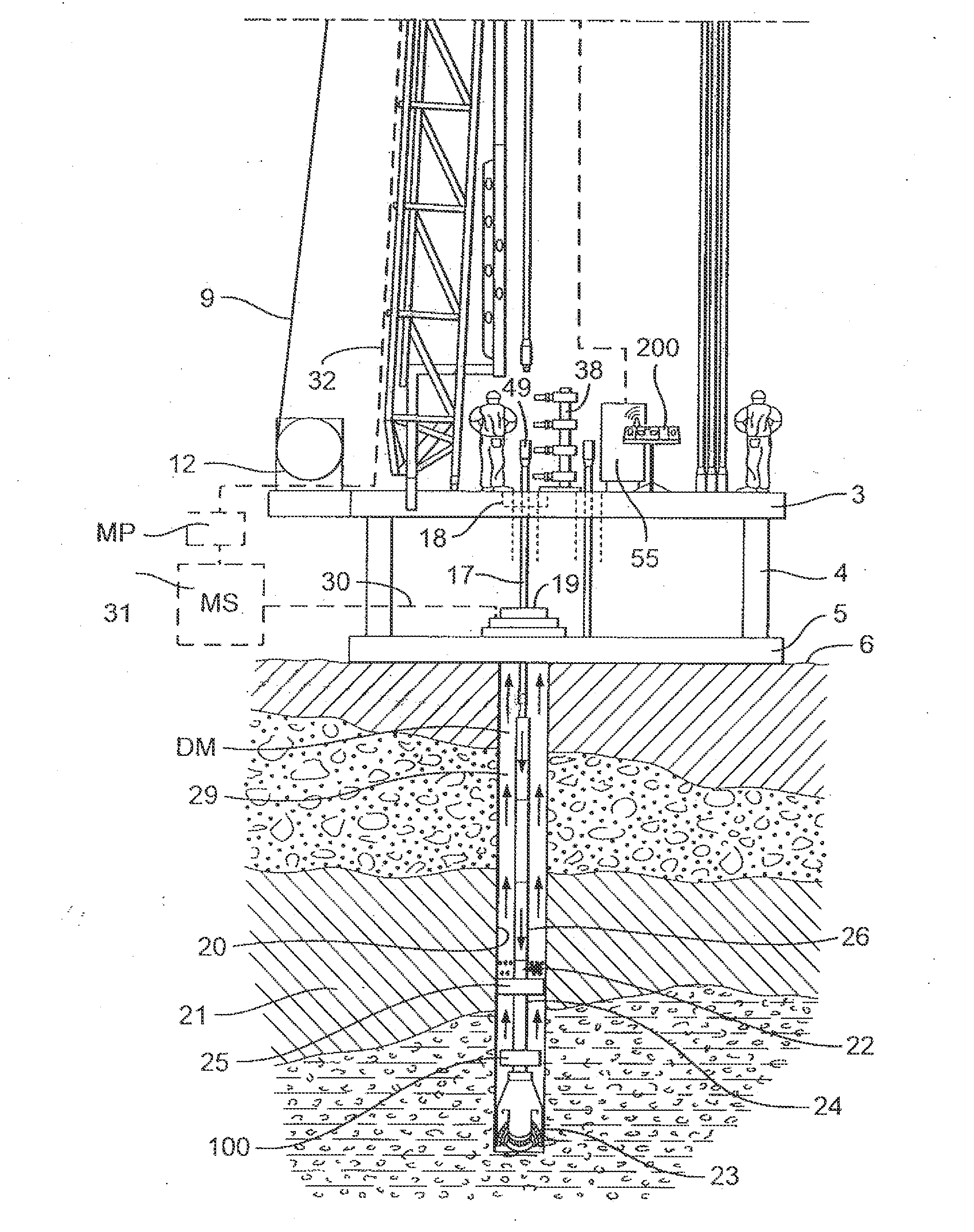
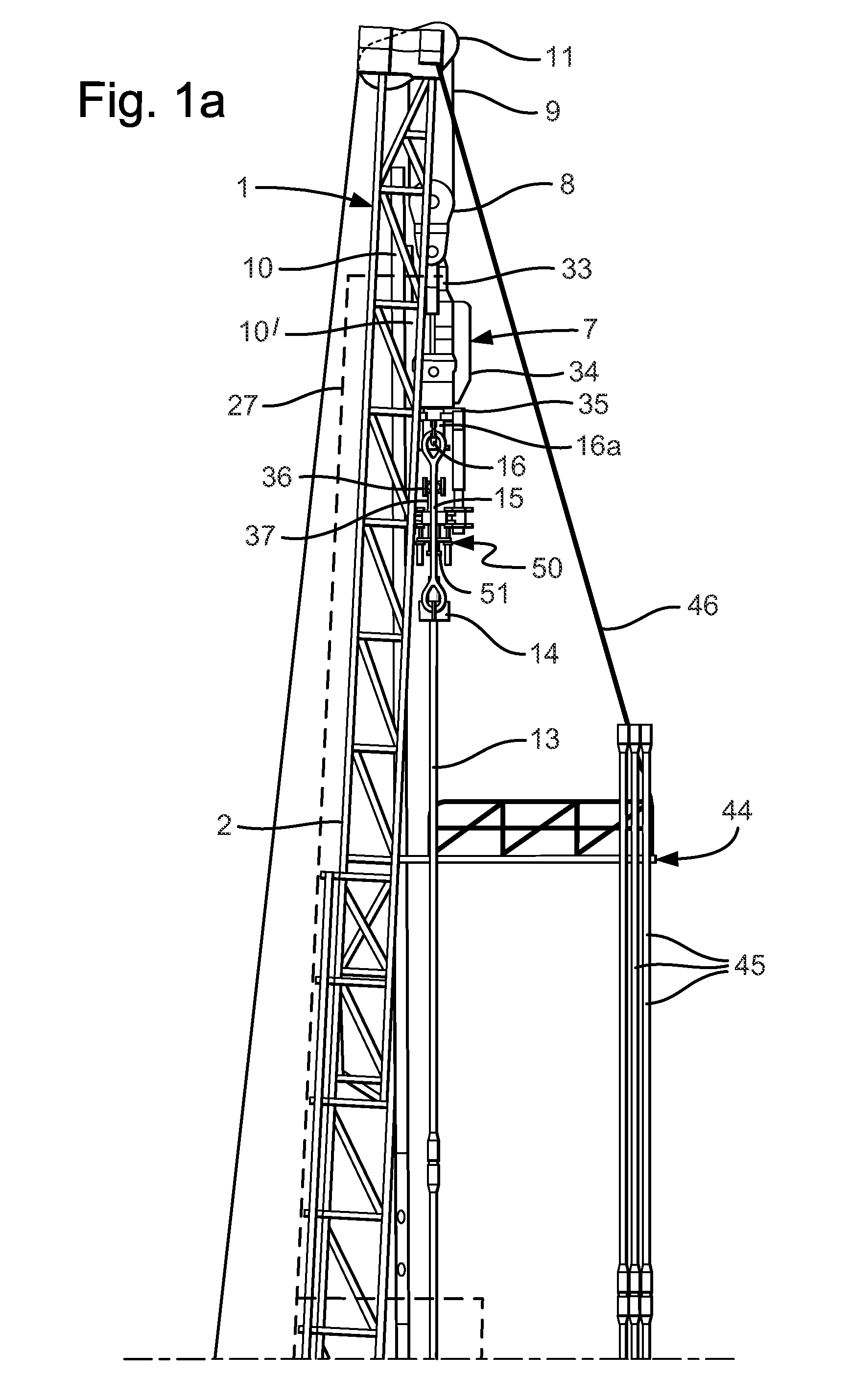
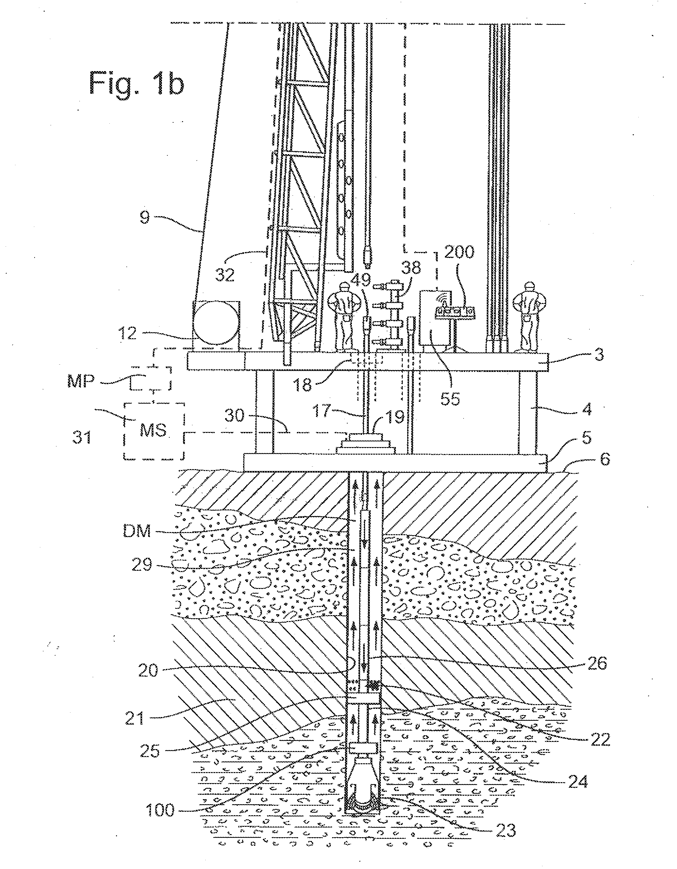
[0054]Referring to FIGS. 1a and 1b there is shown a drilling rig generally identified by reference numeral 1. The drilling rig 1 has a derrick 2 arranged on a drill floor 3 supported on legs 4. The legs 4 are seated on a substructure 5 on ground 6.

[0055]A top drive apparatus 7 is arranged on a carriage 10′ raised and lowered with a travelling block 8 on line 9 along a vertical track 10. The line 9 passes over a crown block 11 located at a top of the derrick 2 and down to a drawworks 12 on the rig floor 3 for reeling the line 9 in and out. A stand of drill pipe 13 depends from an elevator 14. The elevator 14 depends from links 15 which are looped over ears 16 of a swivel 16a of the top drive apparatus 7.

[0056]A drill string 17 passes through a spider 18 in the drill floor 3, through a wellhead 19 into a borehole 20 in formation 21. A bottom hole assembly 22 is arranged on a lower end of the drill string 17. The bottom hole assembly 22 comprises a drill bit 23 connected to a stabilize...


PUM


Abstract

A stabilizer, drill bit, or other component of a bottom hole assembly for use in drilling a borehole includes an elongate and generally cylindrical body, a flow bore in the body, a plurality of outwardly-extending blades, with a valley disposed between adjacent blades. A ring segment that is spaced from the body and extends across at least one valley to define a flow passage through which cuttings-laden drilling mud is conveyed with an upwardly-direct trajectory. The body includes a hole or passageway for conveying drilling mud from the flow bore to between the blades. The passageway terminates in an exit directed toward the flow passage so as to provide fresh drilling mud with a trajectory such that the fluid passes through the flow passage.

Description

CROSS-REFERENCE TO RELATED APPLICATIONS[0001]NoneBACKGROUND[0002]The field of endeavour relates to a stabilizer and a drill bit for use in a drill string. The stabilizer and drill bit preferably, but not exclusively, forms part of a bottom hole assembly of the drill string.[0003]In the drilling of a borehole in the construction of an oil or gas well, a drill bit is arranged at a lower end of a drill string, which is rotated to bore the borehole through a formation. A drilling fluid, referred to herein as “drilling mud,” is pumped through the drill string to the drill bit to lubricate the drill bit and returns carrying drill cuttings in an annulus between an outer wall of the drill string and the borehole. As the drill bit progresses through the formation, stands of drill pipe are added to the drill string. Stands of drill pipe typically comprise two, three or four joints of drill pipe threadedly connected together in a mousehole in a drilling rig floor using an iron roughneck. The s...

Claims


Application Information

Patent Timeline
IPC IPC(8): E21B17/10
CPCE21B17/1078
Inventor TIPPLES, ROBERT PETER DOUGLASWILLIAMS, STEPHENMORRISON, RALPH DALESEGURA, PABEL ANTINIO GADUAN
Owner NOV DOWNHOLE EURASIA LTD
Why Eureka
Try Eureka