
Portable air compressor

a portable, air compressor technology, applied in the direction of positive displacement liquid engine, pump control, pump control, etc., can solve the problems of motor stalling during operation, voltage, or potential difference, beset by air compressor users, etc., to reduce the throat of the valve, reduce the air flow through the valve, and reduce the effect of air flow ra

Inactive Publication Date: 2016-10-06
ALLTRADE TOOLS
View PDF9 Cites 8 Cited by
  • Summary
  • Abstract
  • Description
  • Claims
  • Application Information

AI Technical Summary

Benefits of technology

The invention is a method for providing air to an air compressor by running the motor and drawing air through a valve at a certain delivery rate. The air is then compressed and stored in a tank. The valve is adjusted to decrease the delivery rate of flow. This method allows for the safe and efficient use of air compressors.

Problems solved by technology

However, problems in the art beset users of air compressors.
One problem arises when the compressor draws its electrical power from a cable that may be longer than 20 feet, sometimes even up to 100 feet.
This situation frequently arises when a portable compressor is used on a building site.
However, the impedance of a long power cable may be relatively high, and consequently may have the result that the voltage, or potential difference, available to the compressor is diminished and is not the same as the voltage available at the power outlet.
This tends to have the undesirable result that the motor tends to stall during operation.
Being an induction motor, rather than slowing down it continues at about the same speed as under the design or rated voltage, but tends to lose torque output and then to simply stall where the torque load is greater than the motor's torque output.
The same problem may arise due to different causes.
For example it is found that cold weather may affect the voltage output at the end of an electric current cable, or it may reduce the torque deliverable by the motor.
This can be an exasperating experience to an operator, and there is presently no simple solution to this problem.
As a result, expensive compressors may be found to be quite useless under certain conditions that arise fairly frequently.

Method used


Image

  • Portable air compressor
  • Portable air compressor
  • Portable air compressor

Examples


Embodiment Construction

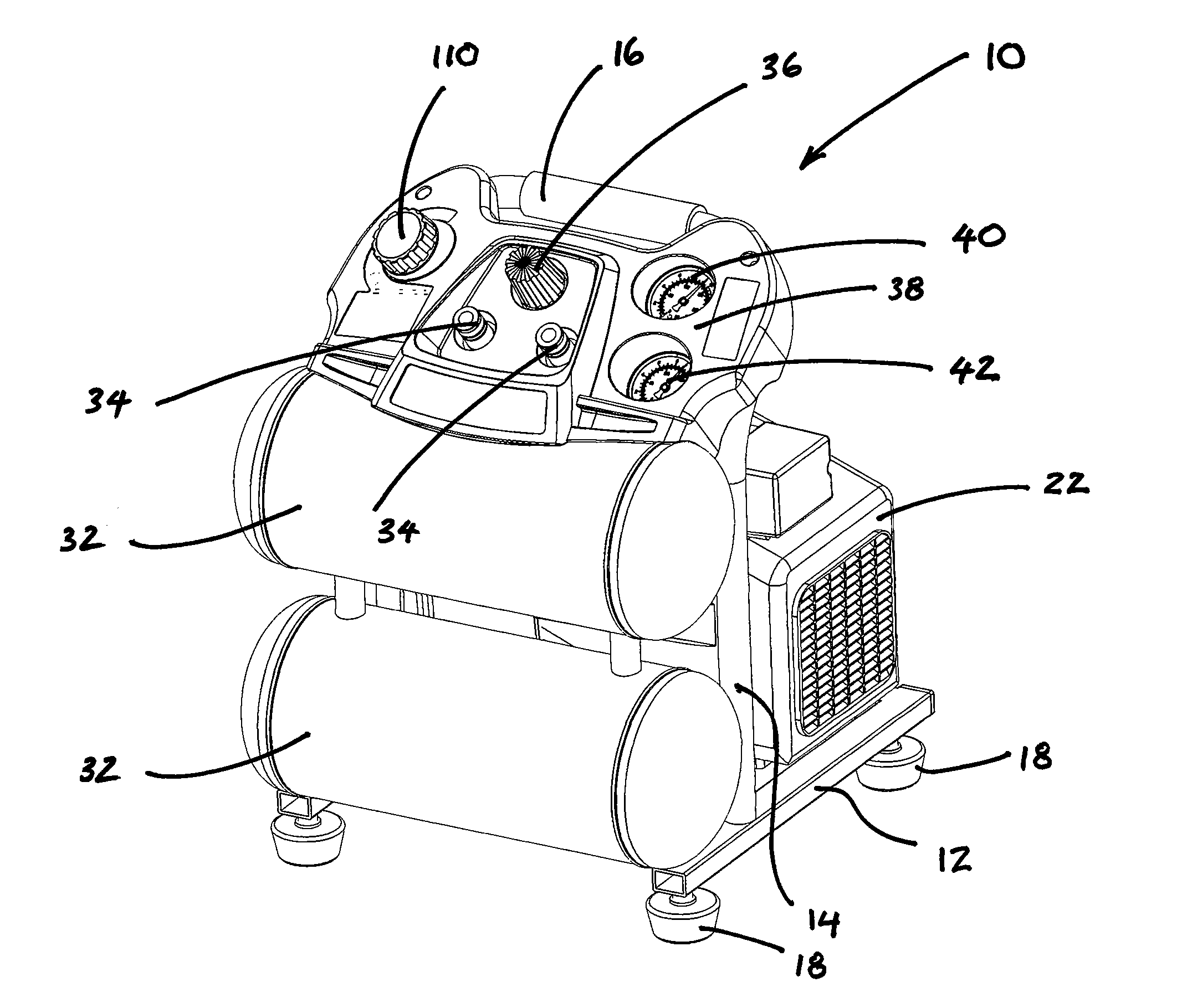
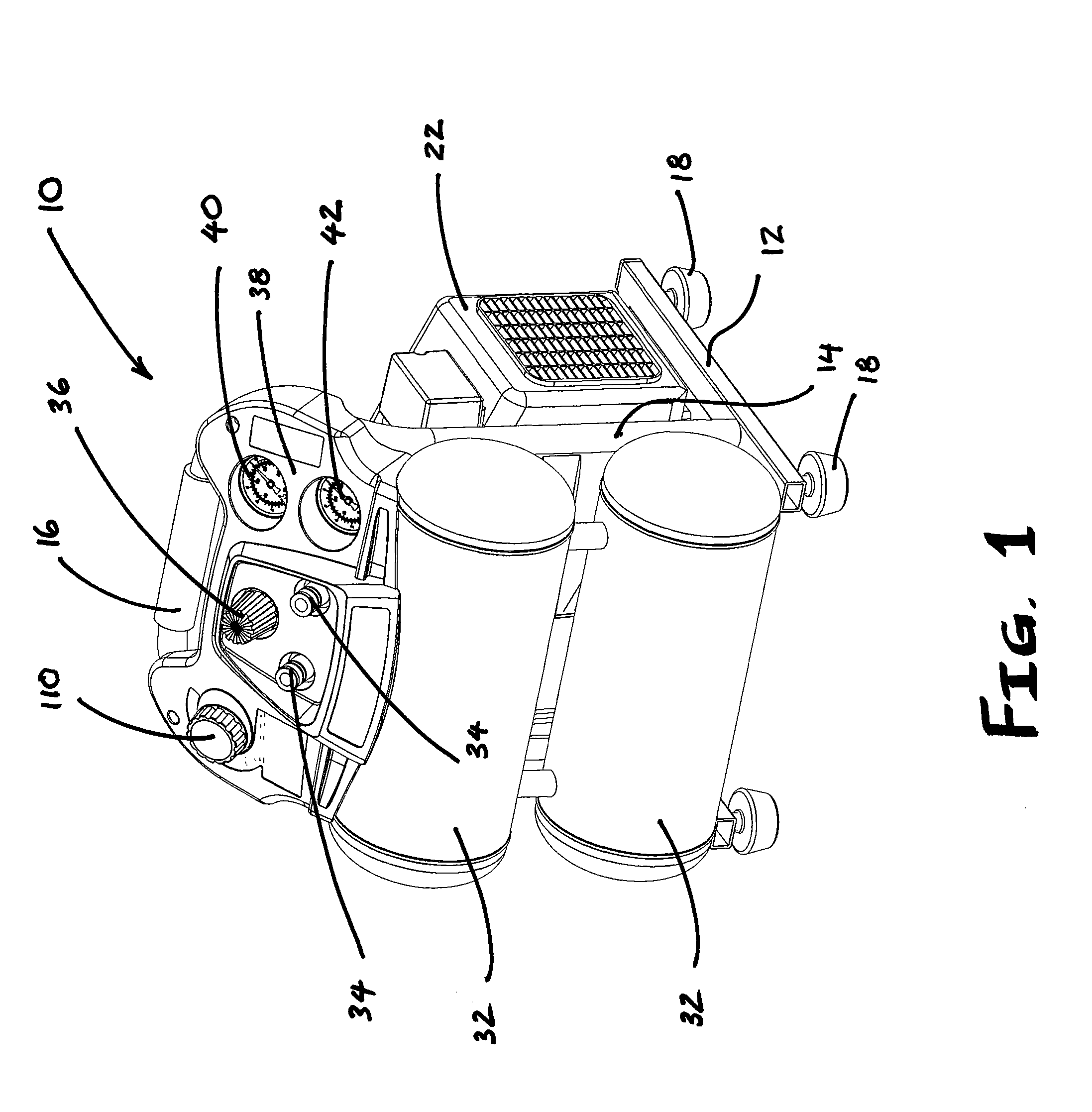
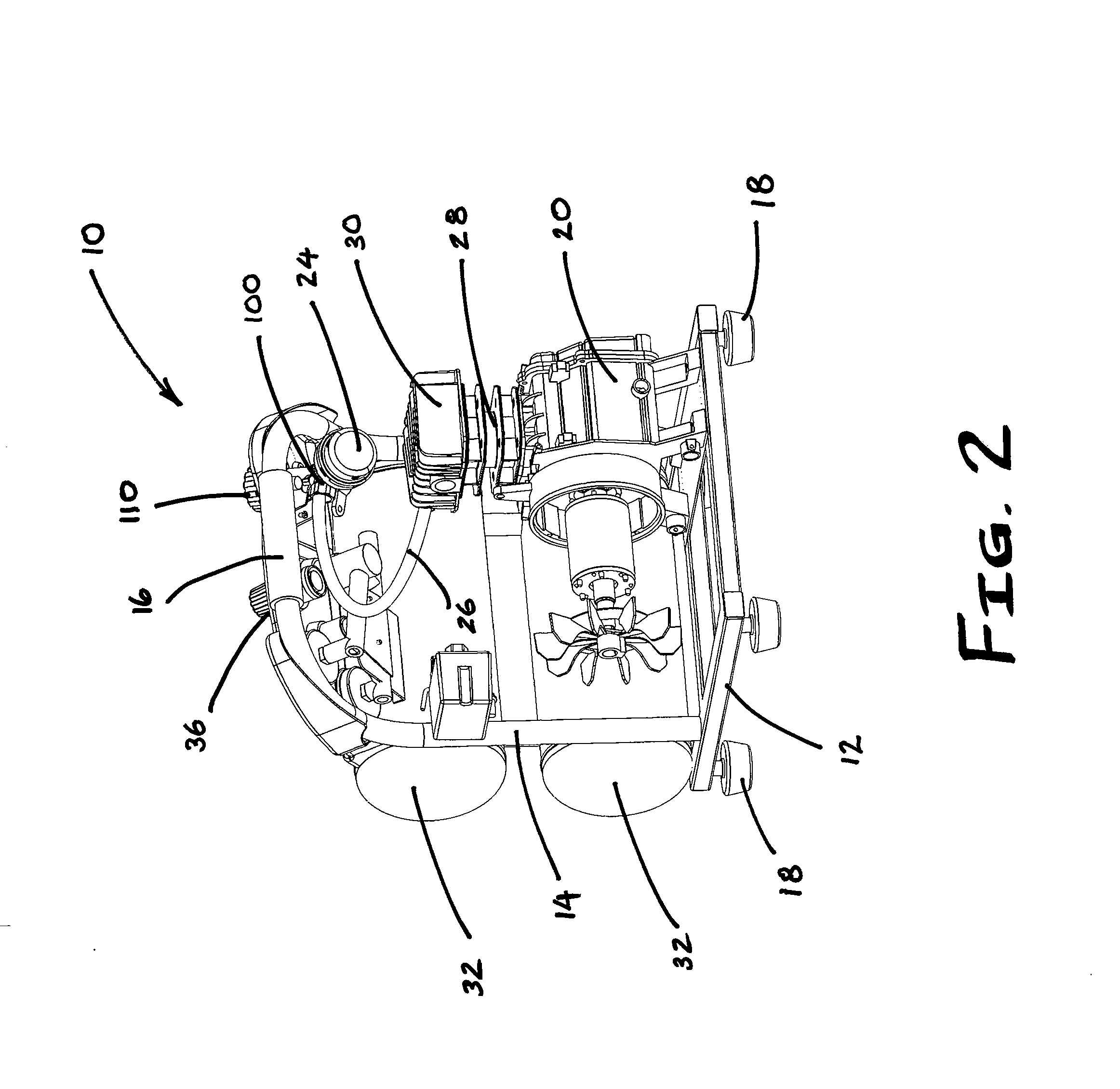
[0014]An embodiment of the invention, which is described with reference to the figures, comprises a mobile air compressor 10 such as that exemplified in FIG. 1 and FIG. 2. A base frame 12 is provided, preferably made of metal tubing. Extending upwardly from the base frame is a handle frame 14 preferably formed from a metal tubing. At the apex of the handle frame is a handle 16, suitable for allowing an operator to lift the entire compressor 10 and move it to a desired location. The base frame may include feet 18, preferably rubber mounted on a threaded rod for height adjustment under known technology. Mounted on the frame is an electric motor 20, best seen in FIG. 2. The motor may be configured to operate on a rated voltage, typically 120 volts in the USA but it differs from country to country. A cover 22 may be provided to enclose the motor as seen in FIG. 1.

[0015]An air intake unit 24 (FIG. 2) is provided to receive an air filter, and to provide an aperture for receiving air at at...


PUM


Abstract

An air compressor comprising an air intake unit for importing air at atmospheric pressure. A cylinder means for compressing air; a storage tank; a first airline extending between the air intake unit and the cylinder means, the first airline being configured to convey air from the air intake unit into the cylinder means; a second airline extending between the cylinder means and the storage tank, the second airline being configured to convey compressed air from the cylinder means to the storage tank; a motor connected to the cylinder means, configured for driving the cylinder means; a valve inserted into the first airline, the valve being configured to be adjustable between a closed condition and an open condition.

Description

BACKGROUND[0001]This application relates to mobile air compressors. Specifically, the application relates to systems for protecting air compressor motors from stalling and burnout under conditions in which the electric power supplied to an air compressor motor may fall below a rated or operational level.[0002]Mobile air compressors are known in the building industry. Such compressors typically comprise an air intake protected by a filter. Air taken into the intake is passed down an airline to a cylinder with an oscillating piston which compresses the air, after which the compressed air is then passed down a further airline to a storage tank, or compressor tank. The cylinder, or compression means, is driven by a motor which is typically designed to operate at a rated voltage to conform with the potential difference which is typically available domestically. In the USA this is about 120 volts, but it differs from country to country. Air flow from the compressor tank passes along a fin...

Claims


Application Information

Patent Timeline
Patent Type & Authority Applications(United States)
IPC IPC(8): F04B41/02F04B49/22F04B35/06
CPCF04B41/02F04B49/225F04B35/06
Inventor HERNANDEZ, HECTOR RAYHARDER, DALETARASHANDEGAN, DAVID
Owner ALLTRADE TOOLS
Learn More