
Anti-reflection optical member

Active Publication Date: 2016-10-06
FUJIFILM CORP
View PDF2 Cites 11 Cited by
  • Summary
  • Abstract
  • Description
  • Claims
  • Application Information

AI Technical Summary

Benefits of technology

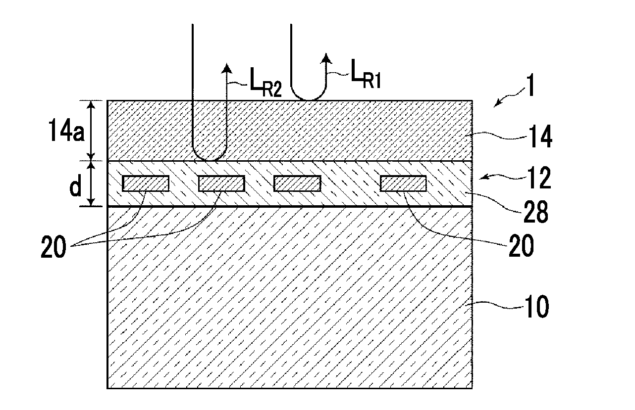
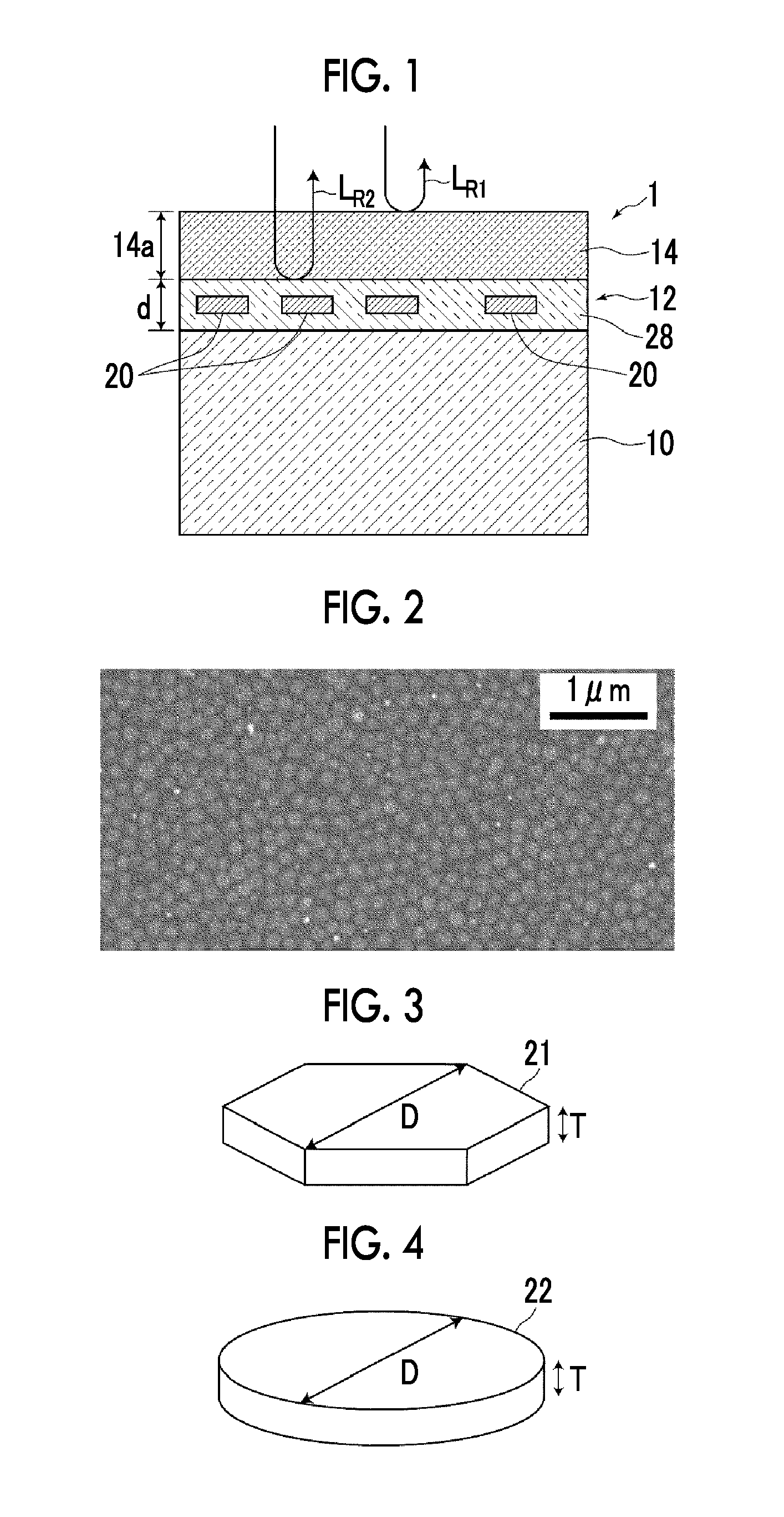
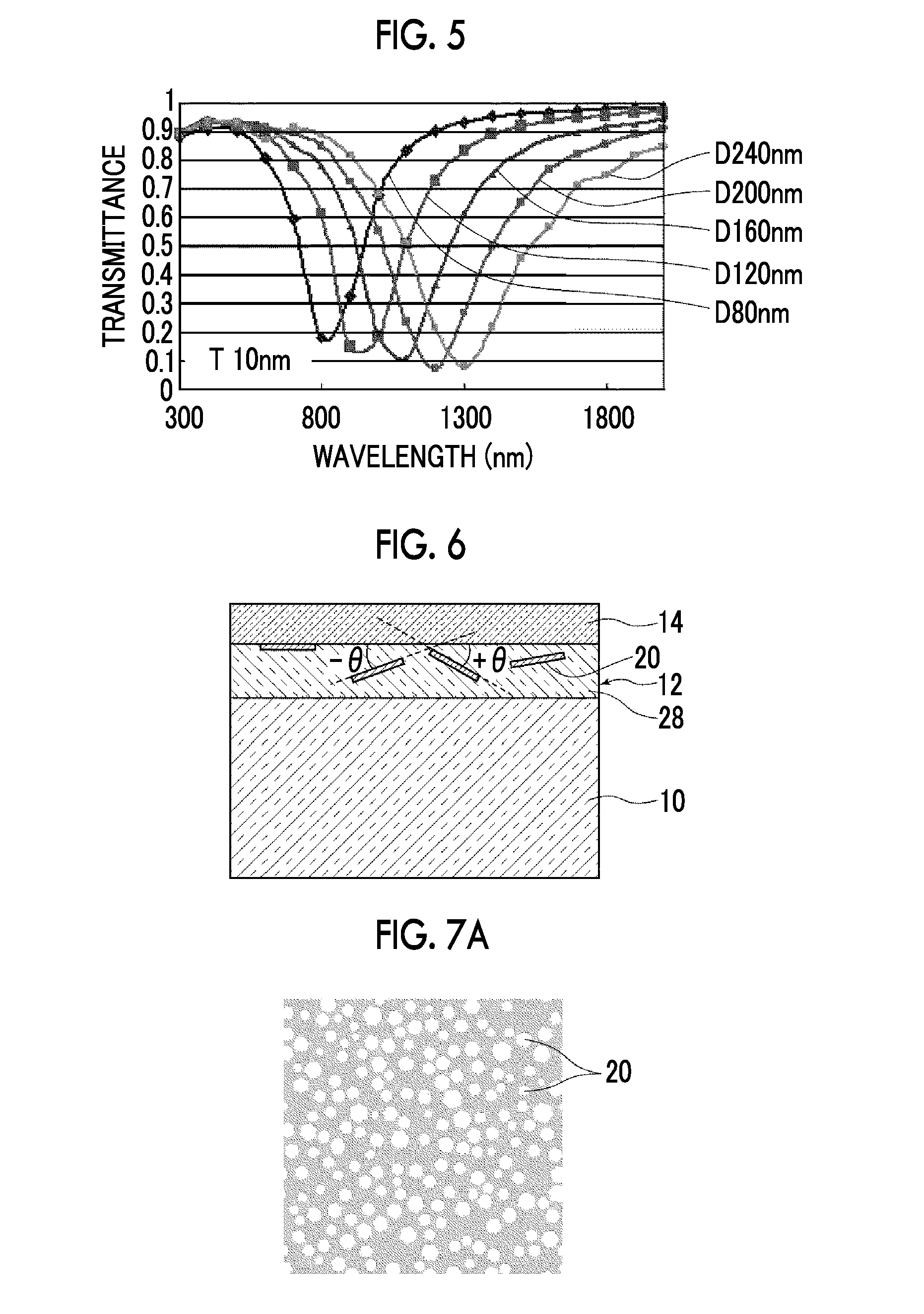
The present invention provides an anti-reflection optical member that can provide a large anti-reflection effect at a wider range of frequencies without reducing the transmission. This is achieved through the use of a metal-microparticle-containing layer that acts as an adjustment layer with a refractive index. The metal microparticles in this layer are flat particles with a high ratio of diameter to thickness, and their main surfaces are oriented in a plane at an angle ranging from 0° to 30° with respect to the surface of the metal-microparticle-containing layer. This results in a low absorbance of the layer with respect to visible light, leading to a high transmittance.

Problems solved by technology

However, in the configuration described in WO2004 / 031813A (JP4400458B), there is a problem in that the transmittance of the incident light is lowered due to absorption.
Further, although it is possible to obtain a large anti-reflection effect with respect to a wavelength of 550 nm, there is a problem in that a bandwidth in which a large anti-reflection effect can be obtained is very narrow.

Method used


Image

  • Anti-reflection optical member
  • Anti-reflection optical member
  • Anti-reflection optical member

Examples


example 1

[0186]The application liquid C1A for the metal-microparticle-containing layer was applied on a surface of a TAC film (FUJITAC, 80 μm, and a refractive index of 1.5) such that an average thickness thereof after drying thereof was 20 nm, by using a wire bar. Thereafter, the liquid was heated, dried, and solidified at 130° C. for one minute, and the metal-microparticle-containing layer was formed. The application liquid D1 for the dielectric layer is applied on the formed metal-microparticle-containing layer such that an average thickness thereof after drying thereof was 60 nm, by using the wire bar. Subsequently, the liquid was heated, dried, and solidified at 130° C. for one minute, and the anti-reflection optical member of Example 1 was obtained.

example 7

[0188]In Example 7, an anti-reflection optical member having a layer configuration, in which the high-refractive index layer 14 shown in FIG. 10 was provided, was produced.

[0189]The application liquid E1 for the high-refractive index layer was applied on the surface of the TAC film (FUJITAC, 80 μm, and the refractive index of 1.5) such that an average thickness thereof after drying thereof was 55 nm, by using the wire bar. Then, the application liquid C1A for the metal-microparticle-containing layer was applied such that an average thickness thereof after drying thereof was 10 nm, by using a wire bar. Thereafter, the liquid was heated, dried, and solidified at 130° C. for one minute, and the metal-microparticle-containing layer was formed. The application liquid D1 for the dielectric layer is applied on the formed metal-microparticle-containing layer such that an average thickness thereof after drying thereof was 70 nm, by using the wire bar. Subsequently, the liquid was heated, dri...


PUM

PropertyMeasurementUnit
Fractionaaaaaaaaaa
Fractionaaaaaaaaaa
Fractionaaaaaaaaaa

Abstract

An anti-reflection optical member has a laminated structure including: a transparent substrate having a first refractive index greater than that of a predetermined medium; a metal-microparticle-containing layer containing metal microparticles; and a dielectric layer having a second refractive index greater than that of the predetermined medium, in this order. At least 60% of the metal microparticles are flat particles with a diameter-to-thickness ratio of 3 or more. Principal planes of the flat metal particles are surface-oriented in the range from 0° to 30° relative to the surface of the metal-microparticle-containing layer. In the metal-microparticle-containing layer, the metal microparticles are disposed without forming a conductive path. The dielectric layer has such a thickness that light reflected at the surface of the dielectric layer of incident light entering the laminated structure from the surface is interfered and canceled by light reflected at the interface between the dielectric layer and the metal-microparticle-containing layer.

Description

CROSS-REFERENCE TO RELATED APPLICATIONS[0001]This application is a Continuation of PCT International Application No. PCT / JP2014 / 005987 filed on Dec. 1, 2014, which claims priority under 35 U.S.C. §119(a) to Japanese Patent Application No. 2013-250138 filed on Dec. 3, 2013 and Japanese Patent Application No. 2014-165347 filed on Aug. 15, 2014. Each of the above applications is hereby expressly incorporated by reference, in its entirety, into the present application.BACKGROUND OF THE INVENTION[0002]1. Field of the Invention[0003]The present invention relates to an anti-reflection optical member that has a function of anti-reflectivity with respect to incident light.[0004]2. Description of the Related Art[0005]In the related art, a display section of a display has been provided with an anti-reflection structure (anti-reflection film) on a translucent member in order to prevent visibility from being lowered due to reflection of an external light source or a landscape.[0006]For example, ...

Claims


Application Information

Patent Timeline
IPC IPC(8): G02B1/111G02B1/16G02B5/00
CPCG02B1/111G02B1/16G02B5/008B32B2264/105B32B2307/204B32B2307/412B32B2307/418B32B2551/00C03C17/34C03C2217/445C03C2217/479G02B1/113G02B5/282
Inventor YASUDA, HIDEKIMATSUNO, RYOUTANI, TAKEHARU
Owner FUJIFILM CORP
Learn More