Unlock instant, AI-driven research and patent intelligence for your innovation.

Current Mode Control DC-DC Converter with Single Step Load Transient Response

a current mode control and converter technology, applied in the direction of dc-dc conversion, power conversion systems, apparatus without intermediate ac conversion, etc., can solve the problem of increasing load current in steps to reach an increased steady-state current which cannot be optimally rapid, and achieve the effect of increasing rapidity

Active Publication Date: 2016-10-06
VIRGINIA TECH INTPROP INC
View PDF12 Cites 14 Cited by
  • Summary
  • Abstract
  • Description
  • Claims
  • Application Information

AI Technical Summary

Benefits of technology

The present invention provides a DC-DC converter that can switch modes quickly for a better response time. This allows for a single step to occur more quickly.

Problems solved by technology

The problem of rapid transient response has proven to be largely intractable, particularly in switching power converters and regulators which, in addition to delays in signal propagation time to alter switching parameters, require several switching cycle periods to make large step-up changes in steady-state current.
Therefore, the increase in load current occurs in steps to reach an increased steady-state current which cannot be optimally rapid since each switching cycle will include some finite period(s) when the input power is interrupted.

Method used


Image

  • Current Mode Control DC-DC Converter with Single Step Load Transient Response
  • Current Mode Control DC-DC Converter with Single Step Load Transient Response
  • Current Mode Control DC-DC Converter with Single Step Load Transient Response

Examples


Embodiment Construction

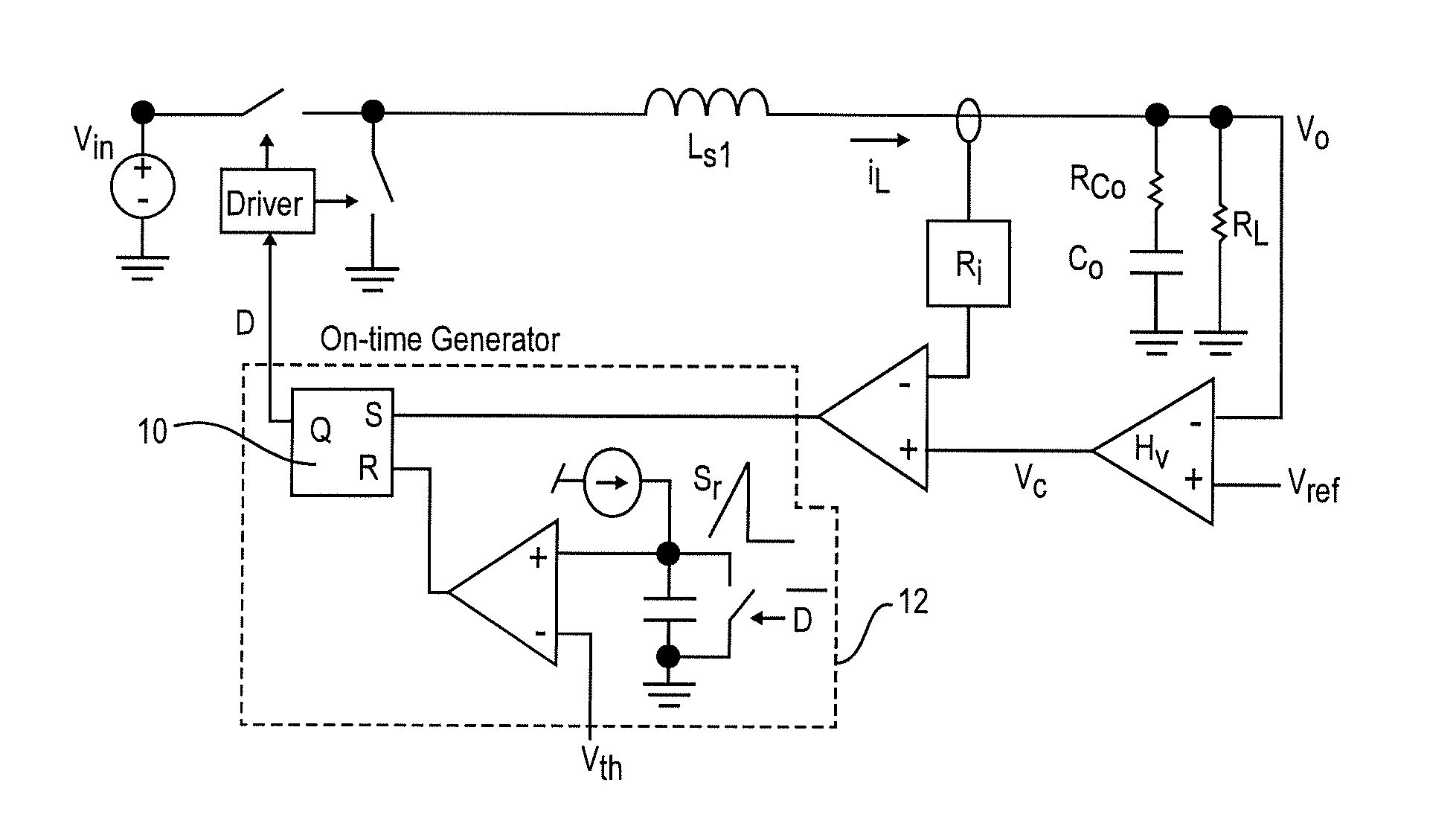
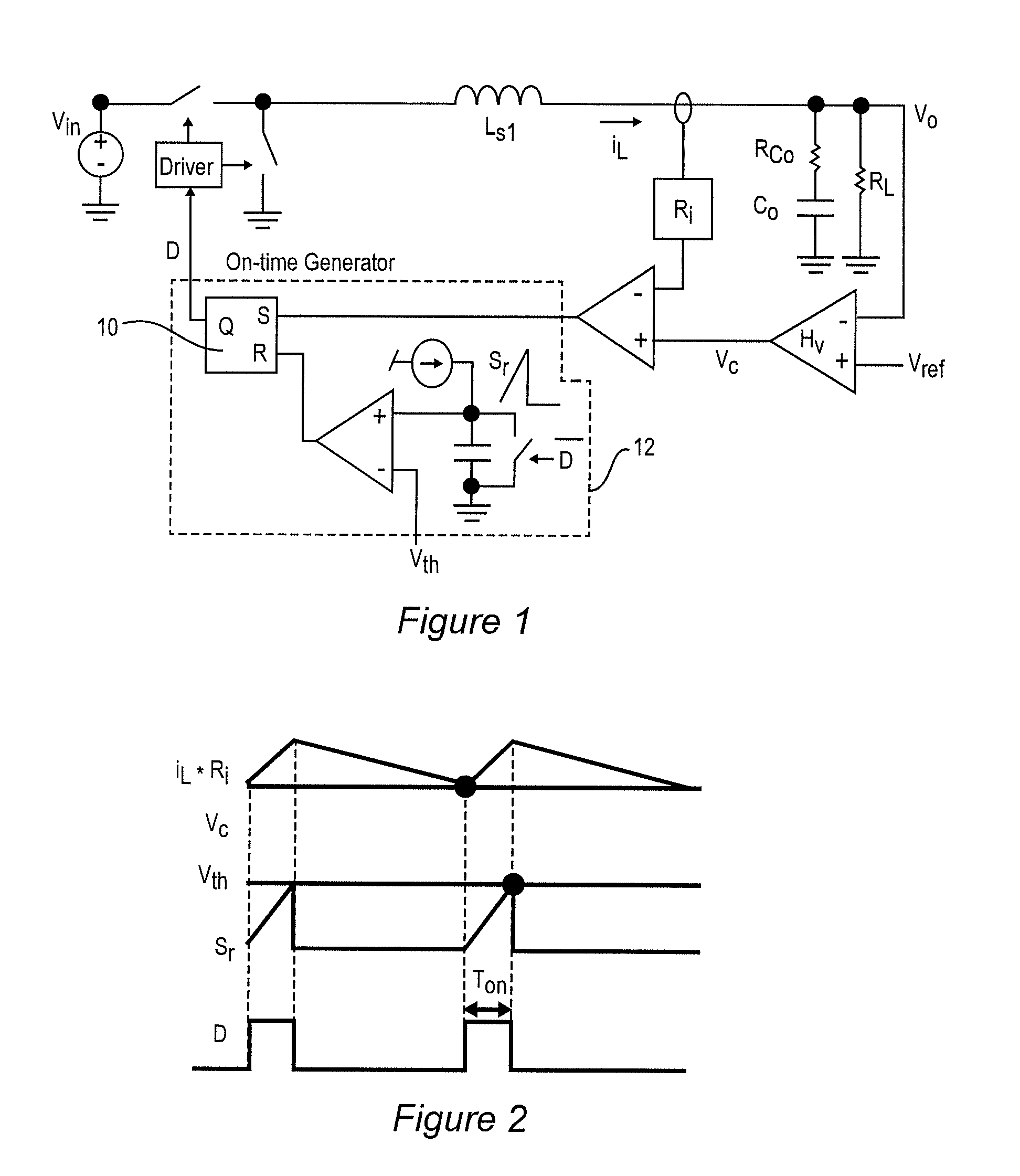
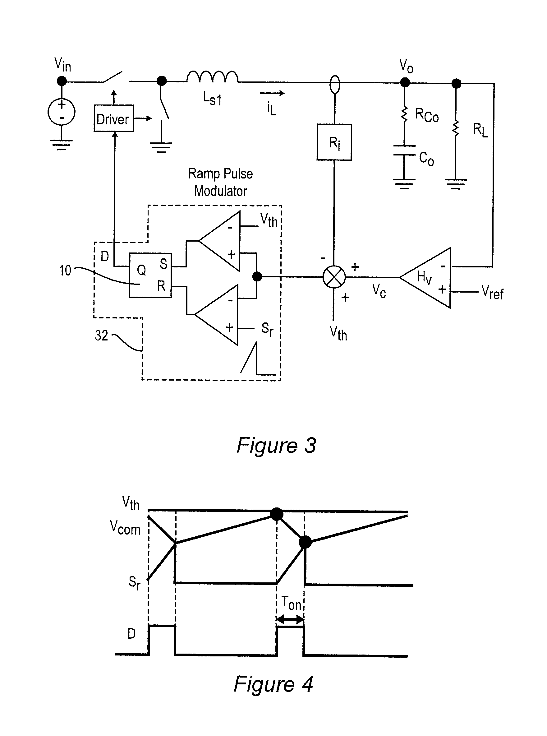
[0034]Referring now to the drawings, and more particularly to FIG. 1, there is schematically shown a generalized control scheme for a constant on-time (COT) power converter. Steady-state operational waveforms of the generalized control arrangement of FIG. 1 is illustrated in FIG. 2. A similar generalized control scheme for a ramp pulse modulation (RPM) power converter and corresponding waveforms are illustrated in FIGS. 3 and 4, respectively. Step-up and Step-down transient waveforms for a COT power converter are illustrated in FIGS. 5 and 6, respectively, and corresponding transient waveforms for an RPM power converter are illustrated in FIGS. 7 and 8, respectively. It should be understood that these Figures are generalized and arranged to facilitate an understanding of the problems addressed by the invention and an appreciation of the performance improvements produced by the invention. Therefore, although the invention is not illustrated in these Figures, no portion of any of FIGS...


PUM


Abstract

A power converter using constant on-time (COT) or ramp pulse modulation (RPM) control achieves more rapid resumption of steady-state operation after a step-up load transient by extending an on-time of a switching pulse by interrupting a ramp voltage waveform that is compared with a threshold that equals a threshold voltage at the termination of a switching pulse or increasing a voltage with which the ramp voltage is compared. These techniques are applied to both single-phase and multi-phase power converters.

Description

CROSS-REFERENCE TO RELATED APPLICATIONS[0001]This application claims benefit of priority of U.S. Provisional Application 62 / 142,048, filed Apr. 2, 2015, which is hereby incorporated by reference in its entirety.FIELD OF THE INVENTION[0002]The present invention generally relates to DC-DC power converters and, more particularly, DC-DC power converters having fast response to load transients.BACKGROUND OF THE INVENTION[0003]At the present time, most electrical power is generated and distributed as alternating current (AC) power for reasons of convenience and economy since AC power can be distributed at high voltage to reduce current and losses over power lines of reduced cost and the voltage locally reduced by transformers even though most electrical and electronic devices other than motors operate from a relatively constant voltage referred to as direct current (DC) which can be produced from an AC power source through use of simple rectifier devices or arrangements. Recently, however...

Claims


Application Information

Patent Timeline
IPC IPC(8): H02M3/04
CPCH02M3/04H02M3/156H02M3/1566
Inventor LI, VIRGINIALIU, PEI-HSINLI, QIANGLEE, FRED C.
Owner VIRGINIA TECH INTPROP INC
Features
  • R&D
  • Intellectual Property
  • Life Sciences
  • Materials
  • Tech Scout
  • Unparalleled Data Quality
  • Higher Quality Content
  • 60% Fewer Hallucinations
Learn More