
Blood oxygenator

a blood oxygenator and oxygenator technology, applied in the field of blood oxygenator devices, can solve the problems of large physical size, large prime volume, large physical size, etc., and achieve the effects of reducing trauma, long-term durability and reliability, and reducing membrane surface area and priming volum

Active Publication Date: 2016-10-13
UNIV OF MARYLAND BALTIMORE
View PDF1 Cites 18 Cited by
  • Summary
  • Abstract
  • Description
  • Claims
  • Application Information

AI Technical Summary

Benefits of technology

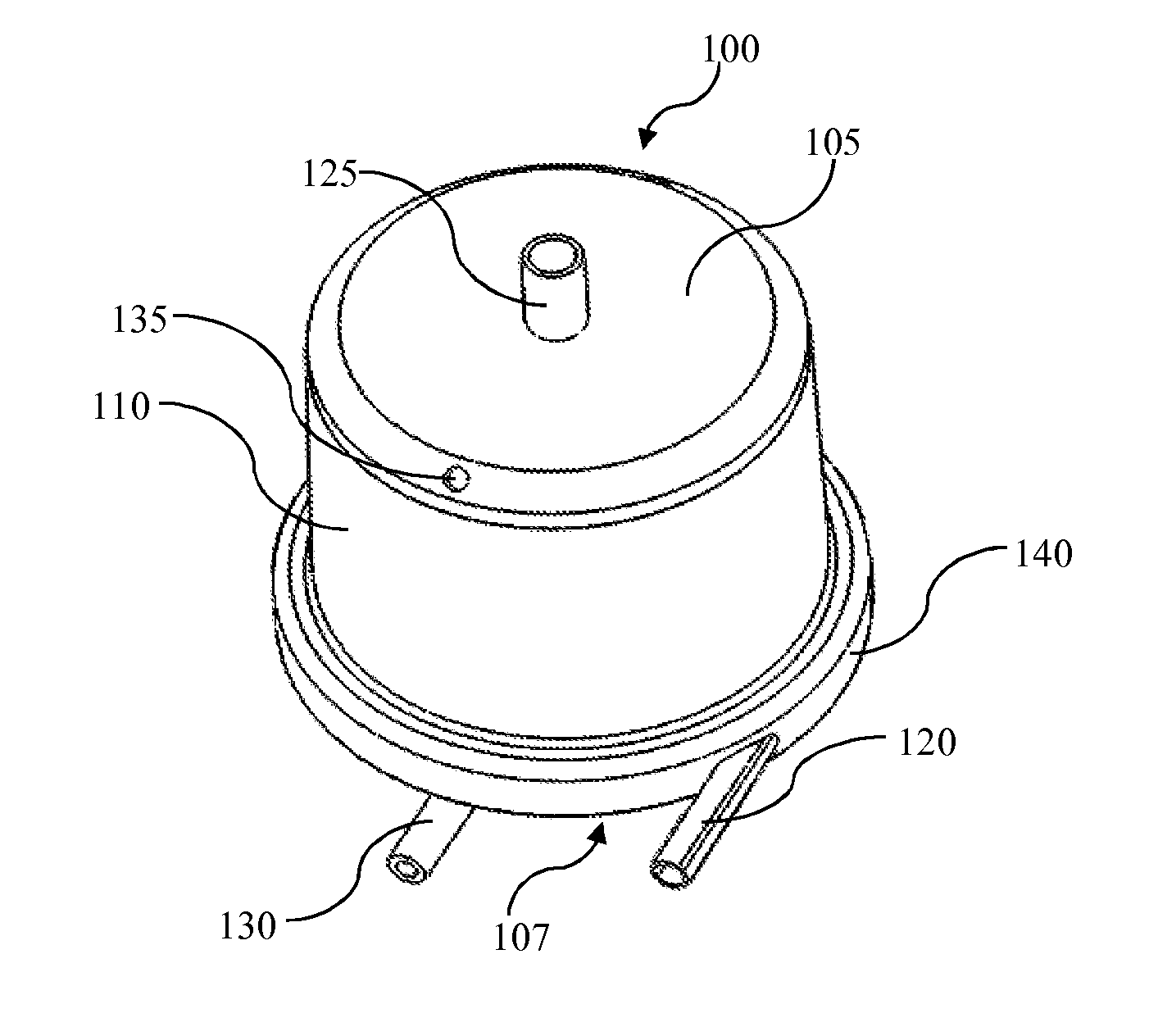
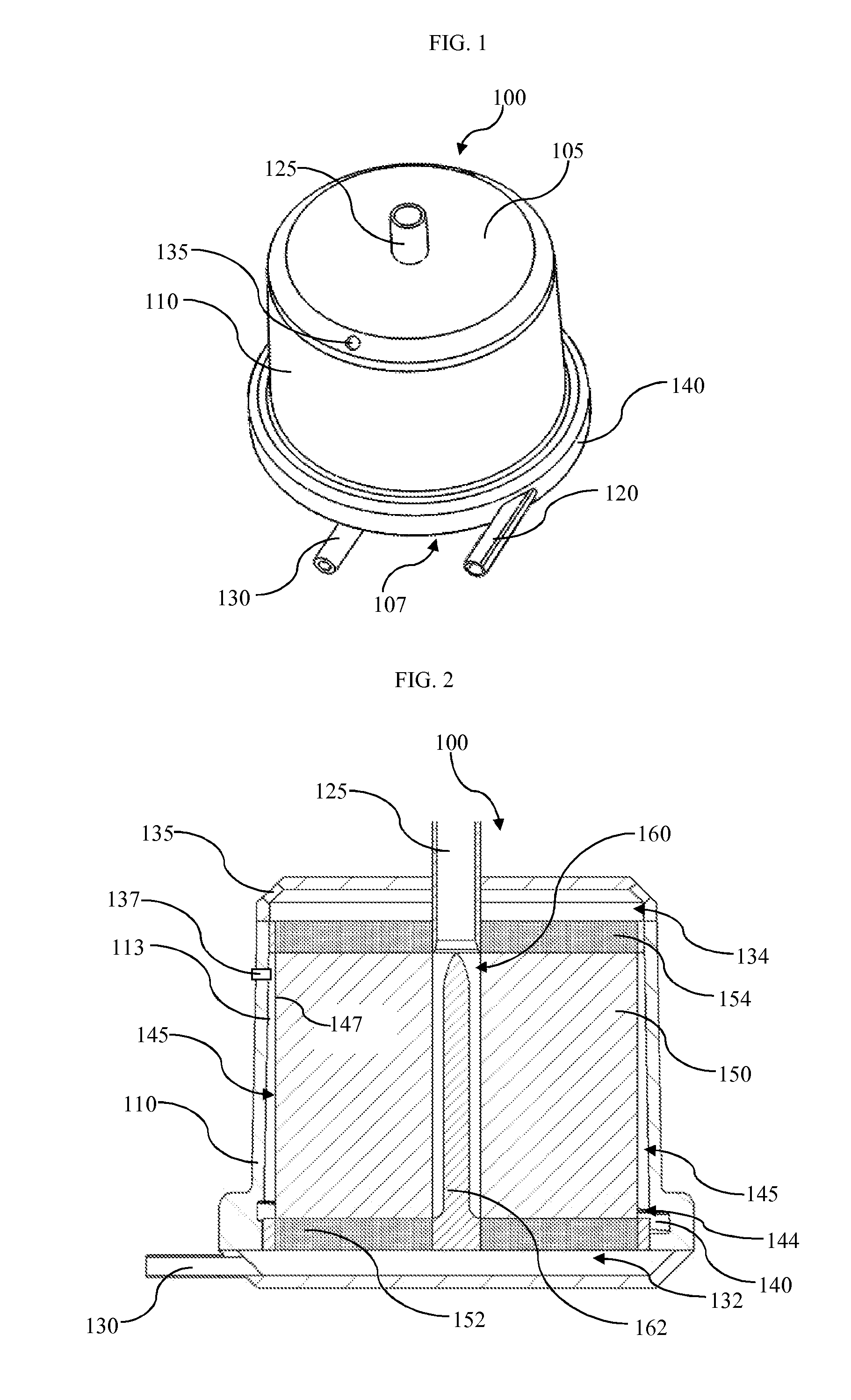
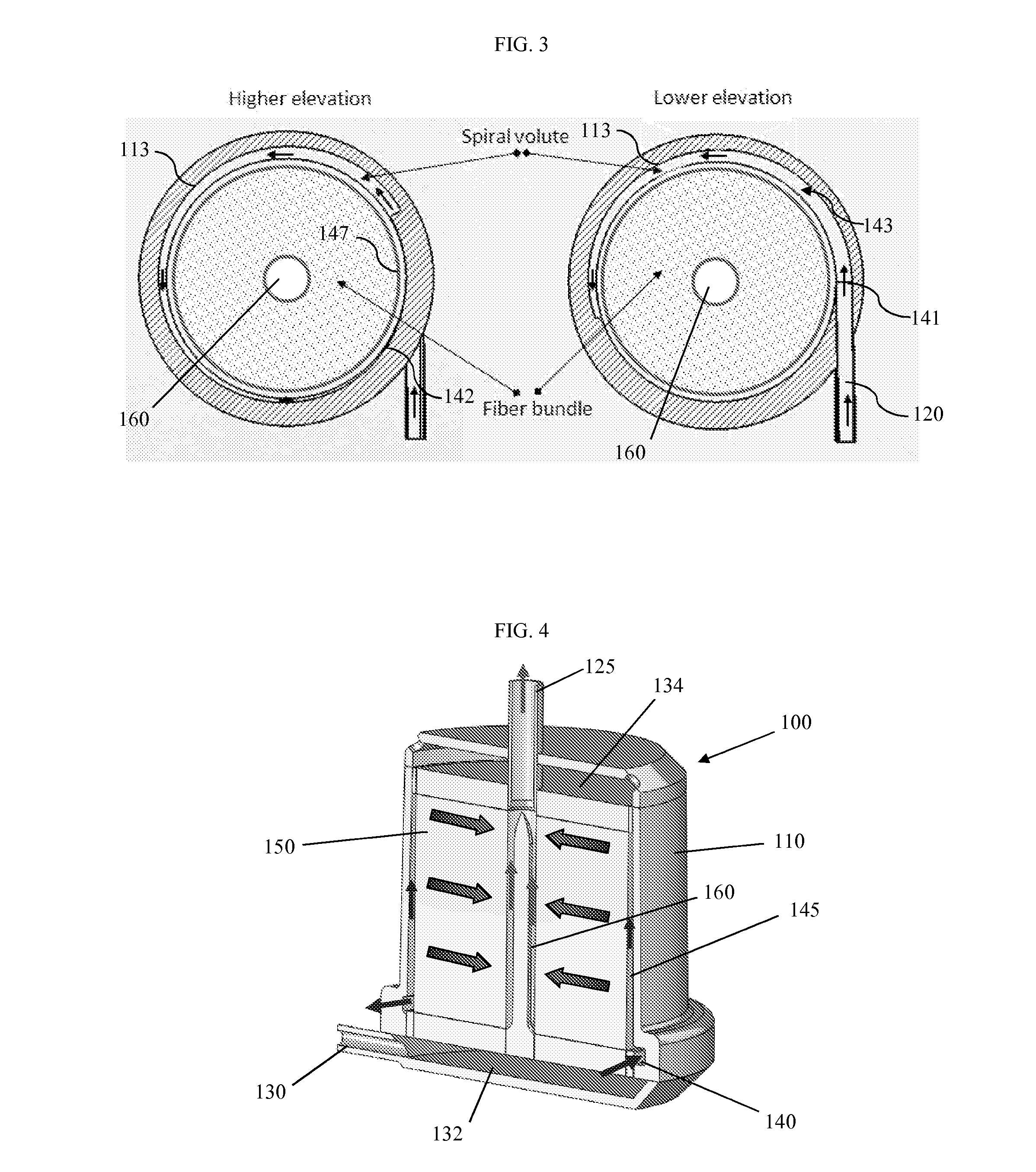
This patent describes a new blood oxygenator that solves problems with current oxygenators by controlling blood flow in a unique way. This leads to a reduction in surface area and volume, and reduces trauma on the patient. The device is also longer-lasting and reliable, and can be used for cardiopulmonary bypass and respiratory support in hospitals and for ambulatory extracapular membrane oxygenation.

Problems solved by technology

Although the membrane blood oxygenators based on the above principles are generally acceptable for cardiopulmonary bypass during open heart surgeries, they have a number of problems when they are used for respiratory support over longer durations (e.g., days to weeks).
They have a relatively large blood-contacting surface area, a large prime volume, and a large physical size with very limited long-term biocompatibility and durability.
The drawbacks of these oxygenators are associated with inherent blood fluid dynamics within these oxygenators, including non-uniform blood flow through the fiber membranes, the existence of laminar boundary flow zones between the blood cells and fiber membranes, and large physical size.
The non-uniform blood flow across the fiber membranes results in hyper- and hypo-perfusion of blood in the flow path.
The gas transfer efficiency can be significantly hindered by the existence of the boundary layer.
The non-uniform blood flow can potentially induce excessive mechanical shear stresses or stasis in the blood flow path in the oxygenators.
These are the major contributing factors to blood activation and thrombosis formation, resulting in limited long-term biocompatibility and durability.
In addition, the large physical size also limits the wearability for ambulatory respiratory support.
One drawback of Mathewson's design is that there exist potential stagnant flow zones between the annular fiber bundle and the outer housing wall.
However, integration of the pump with a blood oxygenator into a system can introduce difficulties for manufacturing and complex flow paths in the integrated system.

Method used


Image

  • Blood oxygenator
  • Blood oxygenator
  • Blood oxygenator

Examples


Embodiment Construction

[0030]The invention summarized above may be better understood by referring to the following description, claims, and accompanying drawings. This description of an embodiment, set out below to enable one to practice an implementation of the invention, is not intended to limit the preferred embodiment, but to serve as a particular example thereof. Those skilled in the art should appreciate that they may readily use the conception and specific embodiments disclosed as a basis for modifying or designing other methods and systems for carrying out the same purposes of the present invention. Those skilled in the art should also realize that such equivalent assemblies do not depart from the spirit and scope of the invention in its broadest form. Likewise, in the following description, for the purposes of explanation, numerous specific details are set forth in order to provide a thorough understanding of the present invention. It will be apparent, however, to one skilled in the art that the ...


PUM


Abstract

A blood oxygenator is disclosed comprising a housing, a blood inlet, a blood outlet, a spiral volute, a gas inlet, an oxygenator fiber bundle, and a gas outlet. The housing encloses the fiber bundle and provides the structure for the blood flow path and connectors. The fiber bundle comprises gas-exchange membranes which transfer oxygen to the blood and remove carbon dioxide when the blood flows across the membranes. The spiral volute guides the blood to flow through the fiber bundle. A gas flow chamber receives sweep gas containing oxygen and distributes the sweep gas into the fiber membranes, which gas is then exchanged with the blood being oxygenated.

Description

GOVERNMENT LICENSE RIGHTS[0001]This invention was made with government support under Grant Numbers HL082631 and HL118372 awarded by the National Institutes of Health. The government has certain rights in the invention.FIELD OF THE INVENTION[0002]This invention relates generally to blood oxygenator devices and methods of their use, and more particularly to blood oxygenators that provide uniform flow and oxygenation.BACKGROUND[0003]Hollow fiber membrane blood oxygenators are the current gold standard for blood oxygenation. These oxygenators typically incorporate one of four blood flow path configurations, as summarized in U.S. Pat. No. 5,462,619: (1) longitudinal (axial) flow through an annular bundle (see U.S. Pat. No. 4,975,247); (2) circumferential flow around an annular bundle (see U.S. Pat. No. 3,794,468); (3) transverse flow across a bundle of substantially rectangular cross-section (see U.S. Pat. No. 5,188,801); and (4) radially outward flow through an annular bundle (see U.S. ...

Claims


Application Information

Patent Timeline
IPC IPC(8): A61M1/16A61M1/10A61M60/113A61M60/232A61M60/38
CPCA61M1/1698A61M1/10A61M2209/088A61M2202/0208A61M2205/366A61M2206/16A61M2205/3334A61M2205/3368A61M2206/10A61M60/113A61M60/38A61M60/232A61M1/3623A61M1/1629
Inventor WU, ZHONGJUNGRIFFITH, BARTLEY P.
Owner UNIV OF MARYLAND BALTIMORE
Learn More