
Energy Storage and Retrieval Systems

a technology applied in the field of energy storage and retrieval, can solve the problems of high-pressure storage tanks, difficult to achieve uniform and stable moving temperature gradients, pressure losses, etc., and achieve the effects of reducing second law losses, increasing temperature, and expanding under-water speed and rang

Active Publication Date: 2016-10-13
KREUGER STEN
View PDF5 Cites 29 Cited by
  • Summary
  • Abstract
  • Description
  • Claims
  • Application Information

AI Technical Summary

Benefits of technology

The present invention uses lithium as a high temperature storage liquid, which has an energy storage density of 2.31 kg / kWh), compared to 3.86 kg / kWh) for lithium-ion batteries and (11.4 kg / kWh) for lead batteries. This allows for quick charging and no limitations on the number of charging cycles. The invention also extends the under-water speed and range of a non-nuclear submarine to 20 knots full power, compared to 4 knots using Stirling engines. The invention uses a PV-cell application and a hot storage medium or reservoir that can store heat at temperatures of 1200° C. The system operates with an energy storage density of only 2 kg salt / kWh of mechanical energy, compared to 74 kg / kWh for the high temperature salt storage system at Andasol in Spain. The invention effectively divides the cycle into multiple loops and / or selective pairing of hot and cold storage liquids, which compensates for second law losses. The invention also uses a wide temperature range for the storage fluid, which increases the storage capacity. This allows for direct electric heating of the high temperature heat storage fluid when electricity is cheap and facilitates the transfer of the heat storage liquid between the tanks.

Problems solved by technology

The disadvantages of this approach include pressure losses when the working gas traverses through the heat storage and the expensive high pressure storage tanks.
There are also difficulties with a uniform stable moving temperature gradient in the storage tanks.

Method used


Image

  • Energy Storage and Retrieval Systems
  • Energy Storage and Retrieval Systems
  • Energy Storage and Retrieval Systems

Examples


Embodiment Construction

[0051]Reference will now be made in detail to various embodiments of the invention, examples of which are illustrated in the accompanying drawings. While the invention will be described in conjunction with the following embodiments, it will be understood that the descriptions are not intended to limit the invention to these embodiments. On the contrary, the invention is intended to cover alternatives, modifications and equivalents that may be included within the spirit and scope of the invention. Furthermore, in the following detailed description, numerous specific details are set forth in order to provide a thorough understanding of the present invention. However, it will be readily apparent to one skilled in the art that the present invention may be practiced without these specific details. In other instances, well-known methods, procedures, components, and materials have not been described in detail so as not to unnecessarily obscure aspects of the present invention.

[0052]The tec...


PUM


Abstract

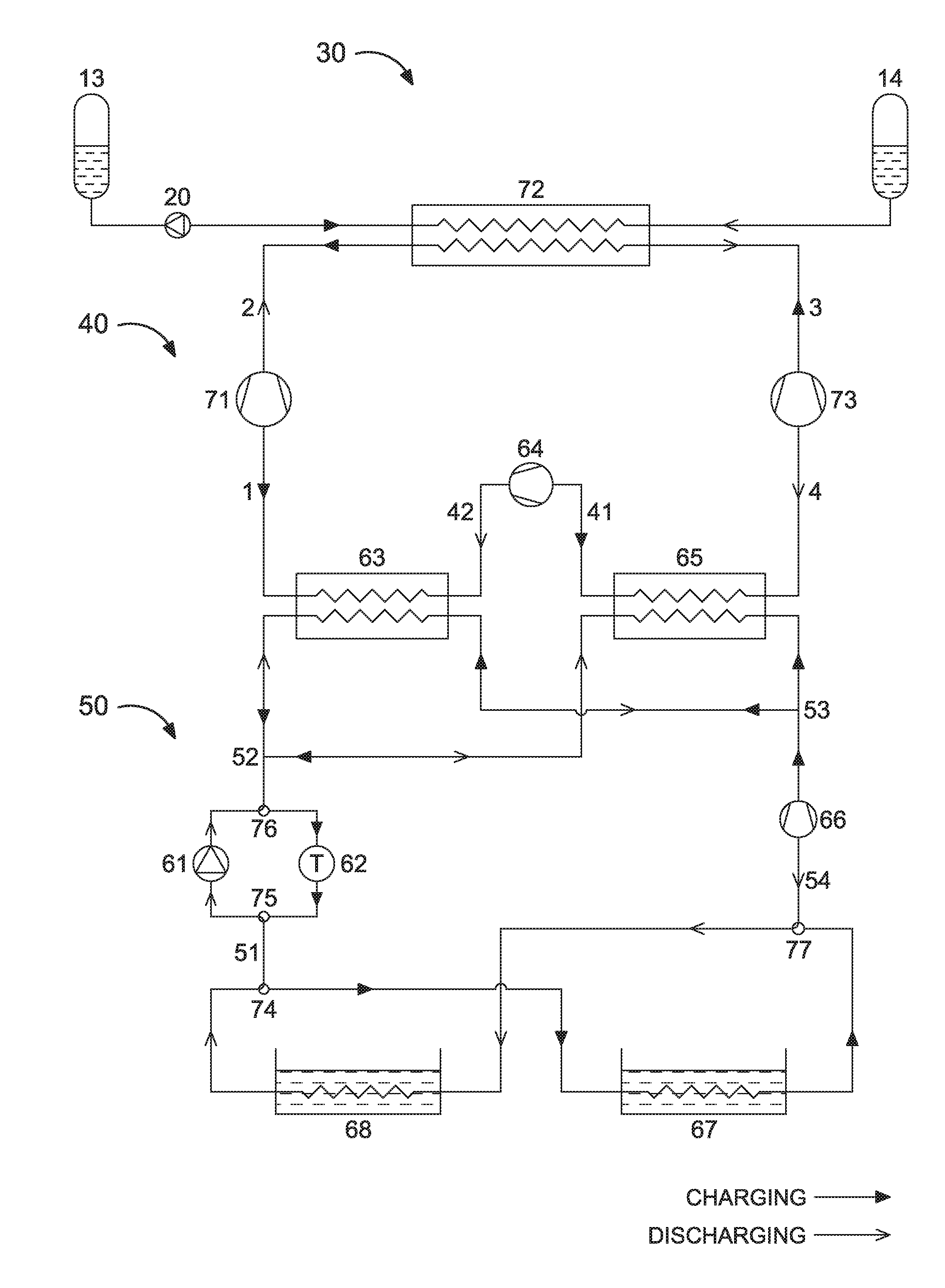
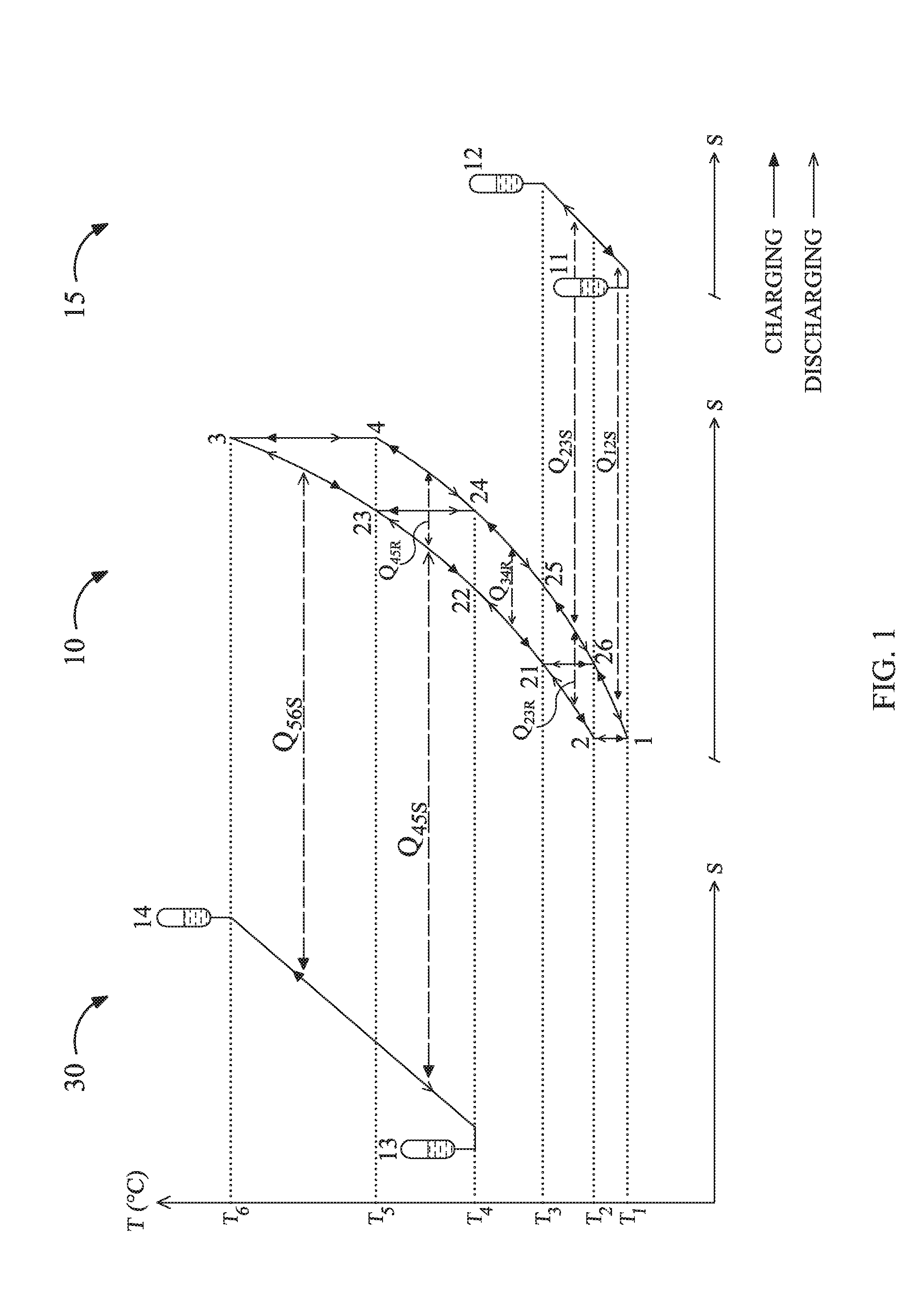
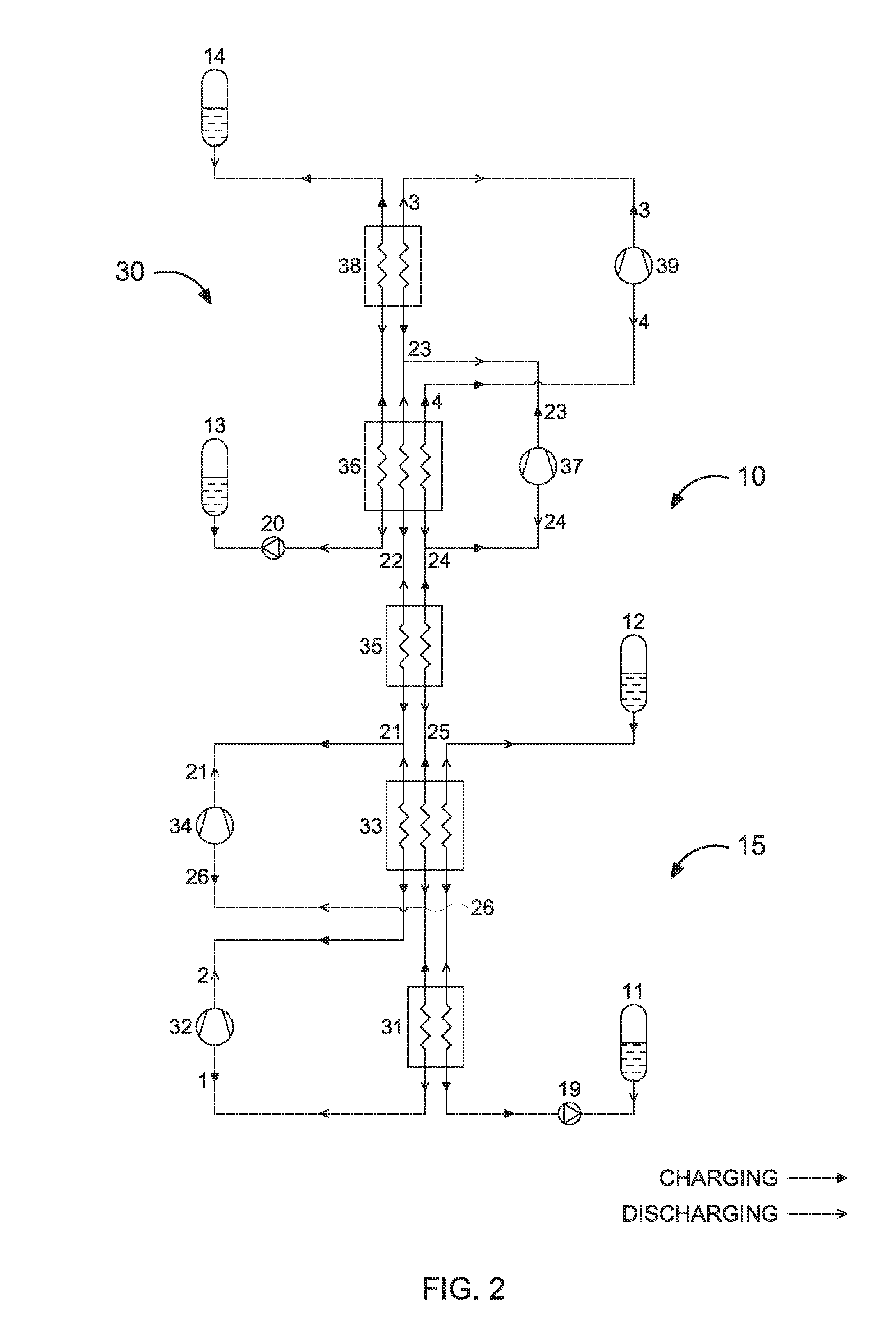
Systems and methods for storing and retrieving thermo-mechanical energy are disclosed. The systems and methods include a thermodynamic cycle (e.g., a reversible transcritical, trilateral, Brayton or Rankine / vapor compression cycle) that includes a plurality of loops and works as a heat pump in charging mode and as a heat engine in discharging mode. Each loop in the thermodynamic cycle includes pressure increasing and decreasing devices, high and low pressure heat exchanging devices, and the same or different working fluid. The system further includes one or more heat storage chains with hot and cold storage reservoirs and a heat storage fluid. At least one of the high and low pressure heat exchanging devices is a gradient heat exchanging device that exchanges heat with the heat storage chain. Also, at least one other high or low pressure heat exchanging device exchanges heat with a separate heat storage device or a heat source or sink.

Description

RELATED APPLICATION(S)[0001]The present application claims priority to U.S. Provisional Pat. Appl. No. 62 / 146,186, filed Apr. 10, 2015 (Atty. Docket No. SK-004-PR), incorporated herein by reference in its entirety. The present application may also be related to U.S. patent application Ser. Nos. 14 / 512,168 and / or 14 / 658,617, respectively filed on Oct. 10, 2014 and Mar. 16, 2015, the relevant portions of which are incorporated herein by reference.FIELD OF THE INVENTION[0002]The present invention generally relates to the field of energy storage and retrieval. More specifically, embodiments of the present invention pertain to methods and systems that use thermal energy for storing and retrieving thermal and / or mechanical energy.DISCUSSION OF THE BACKGROUND[0003]Energy storage is important for sustainable energy supply from sources such as wind and the sun.[0004]Energy stored as heat and retrieved as mechanical energy has been around ever since the liquid air car (U.S. Pat. No. 657,124 f...

Claims


Application Information

Patent Timeline
Patent Type & Authority Applications(United States)
IPC IPC(8): F01K23/12F28D20/02F01K23/06F03G6/06F01K3/02
CPCF01K23/12F03G6/06F28D20/02F01K23/06F01K3/02F28D20/0034F28D2020/0082F05D2260/42F01K5/00Y02E10/46F02C1/05F02C1/10Y02E60/14F03G6/068
Inventor KREUGER, STEN
Owner KREUGER STEN
Learn More