Grinding Tool and Method of Manufacturing the Same

a technology of grinding tools and grinding pads, which is applied in the direction of manufacturing tools, grinding devices, and abrasive surface conditioning devices, etc., can solve the problems of reducing the grinding action of the grinding pad and making the grinding tool more expensive to manufactur

Active Publication Date: 2016-10-20
KINIK
View PDF20 Cites 47 Cited by
  • Summary
  • Abstract
  • Description
  • Claims
  • Application Information

AI Technical Summary

Problems solved by technology

After the polishing pad is used over a period of time, the grinding action of the polishing pad may diminish.
This requires increasing the quantity of abrasive elements on the grinding tool, which makes the grinding tool more expensive to manufacture.

Method used


Image

  • Grinding Tool and Method of Manufacturing the Same
  • Grinding Tool and Method of Manufacturing the Same
  • Grinding Tool and Method of Manufacturing the Same

Examples


Embodiment Construction

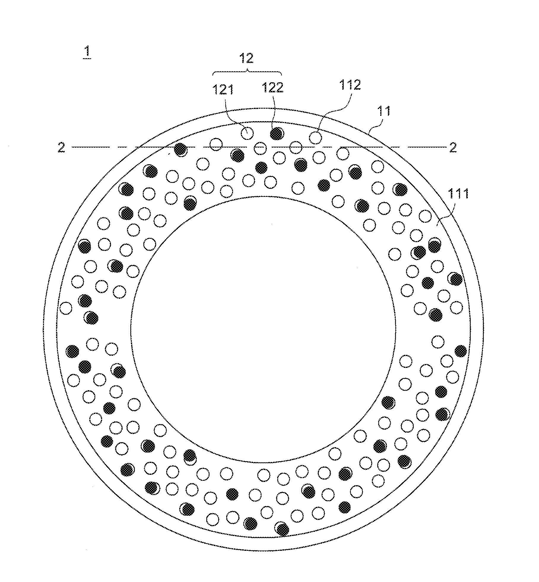
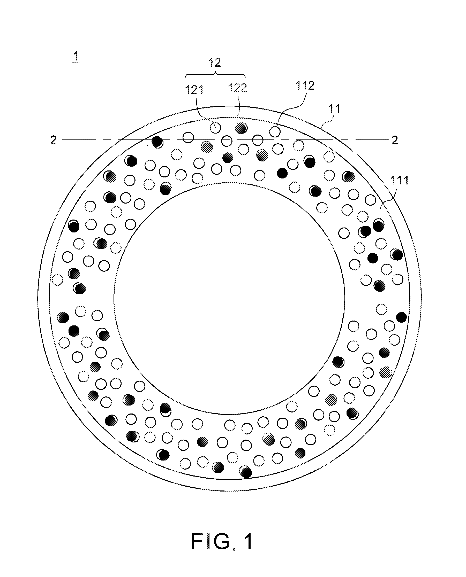
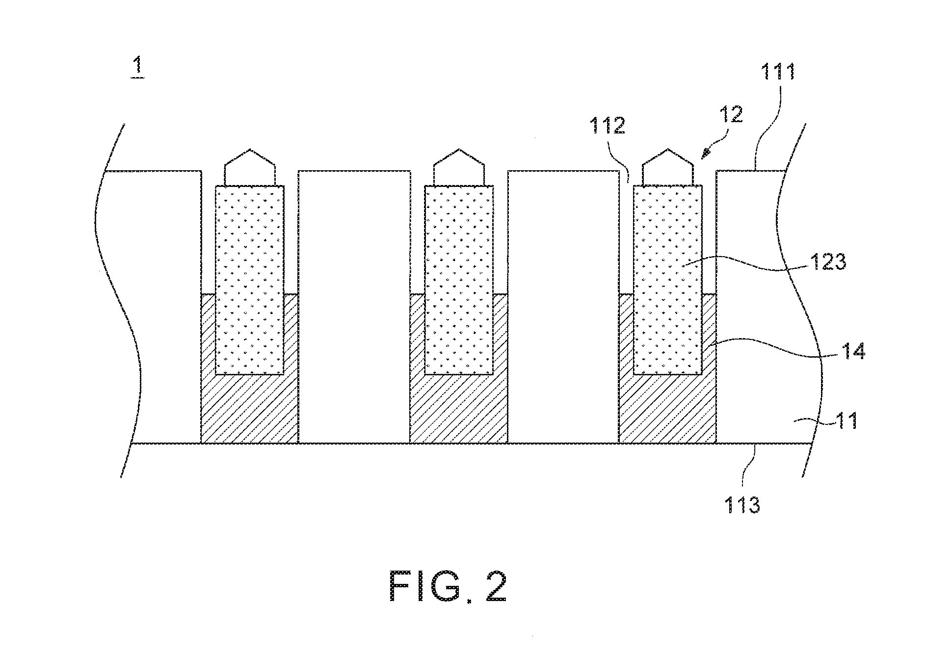
[0024]FIG. 1 is a schematic planar view illustrating an embodiment of a grinding tool 1, and FIG. 2 is a schematic cross-sectional view taken along section plane 2 shown in FIG. 1 illustrating support posts 123 affixed in holes 112 of the grinding tool 1. In one example of implementation, the grinding tool 1 can be used as a conditioner for a polishing pad in chemical mechanical polishing (CMP) processes. Referring to FIGS. 1 and 2, the grinding tool 1 can include a substrate 11 and a plurality of abrasive particles 12. The substrate 11 can have a working surface 111 and a bottom surface 113 on two opposite sides, and a plurality of holes 112 respectively opening on the working surface 111 and the bottom surface 113. The abrasive particles 12 can be respectively affixed to a plurality of support posts 123, and the support posts 123 can be respectively attached in the holes 112 of the substrate 11 via bonding layers 14. The bonding layers 14 can be exposed outward on the bottom surfa...


PUM

PropertyMeasurementUnit
lengthaaaaaaaaaa
lengthaaaaaaaaaa
angleaaaaaaaaaa

Abstract

A grinding tool includes a substrate having a working surface, and a plurality of abrasive particles distributed over the working surface and protruding outward from the working surface, wherein at least some of the abrasive particles are machined to form abrasive particles respectively having an obliquely truncated pyramid shape. Some embodiments described herein also include a method of manufacturing the grinding tool.

Description

CROSS-REFERENCE TO RELATED APPLICATION(S)[0001]This application claims priority to Taiwan Patent Application No. 104112579 filed on Apr. 20, 2015, the disclosure of which is incorporated herein by reference.BACKGROUND[0002]1. Field of the Invention[0003]The present invention relates to grinding tools used in chemical mechanical polishing techniques.[0004]2. Description of the Related Art[0005]Grinding and / or polishing techniques are generally applied to create a desirable surface roughness or planarity on a rigid part, such as metal, ceramic or glass parts, or semiconductor wafers. To this purpose, the grinding and / or polishing techniques use tools having abrasive elements that can wear the hard surface.[0006]A well known polishing technique is the chemical mechanical polishing (CMP) technique employed in semiconductor fabrication processes. CMP uses corrosive chemical slurry in conjunction with a polishing pad to remove undesired residues and planarize a wafer surface, which can be...

Claims


Application Information

Patent Timeline
Patent Type & Authority Applications(United States)
IPC IPC(8): B24B53/017B24D18/00B24D7/06
CPCB24B53/017B24D18/0018B24D18/00B24D7/066B24B37/26B24D3/00B24D7/06B24D9/08
Inventor CHOU, JUI-LINCHIU, CHIA-FENGLIAO, WEN-JENSU, XUE-SHEN
Owner KINIK
Why Eureka
Try Eureka