System for inspecting rail with phased array ultrasonics

a phased array and ultrasonic technology, applied in the field of railway rail inspection, can solve the problems of limited adjustment and missed defects

Inactive Publication Date: 2016-10-20
TRANSPORTATION TECH CENT
View PDF2 Cites 31 Cited by
  • Summary
  • Abstract
  • Description
  • Claims
  • Application Information

AI Technical Summary

Benefits of technology

[0013]The present invention provides a system for ultrasonic rail inspection that addresses the deficiencies of traditional RSU configurations by enabling an optimal configuration of phased array ultrasonic probes and focal laws to inspect railroad rail. This approach compensates for the effects of rail profile wear without introducing any external profile measurement hardware.

Problems solved by technology

For example, if wear is only detected on the gage side, adjustments may be limited to only th

Method used


Image

  • System for inspecting rail with phased array ultrasonics
  • System for inspecting rail with phased array ultrasonics
  • System for inspecting rail with phased array ultrasonics

Examples


Embodiment Construction

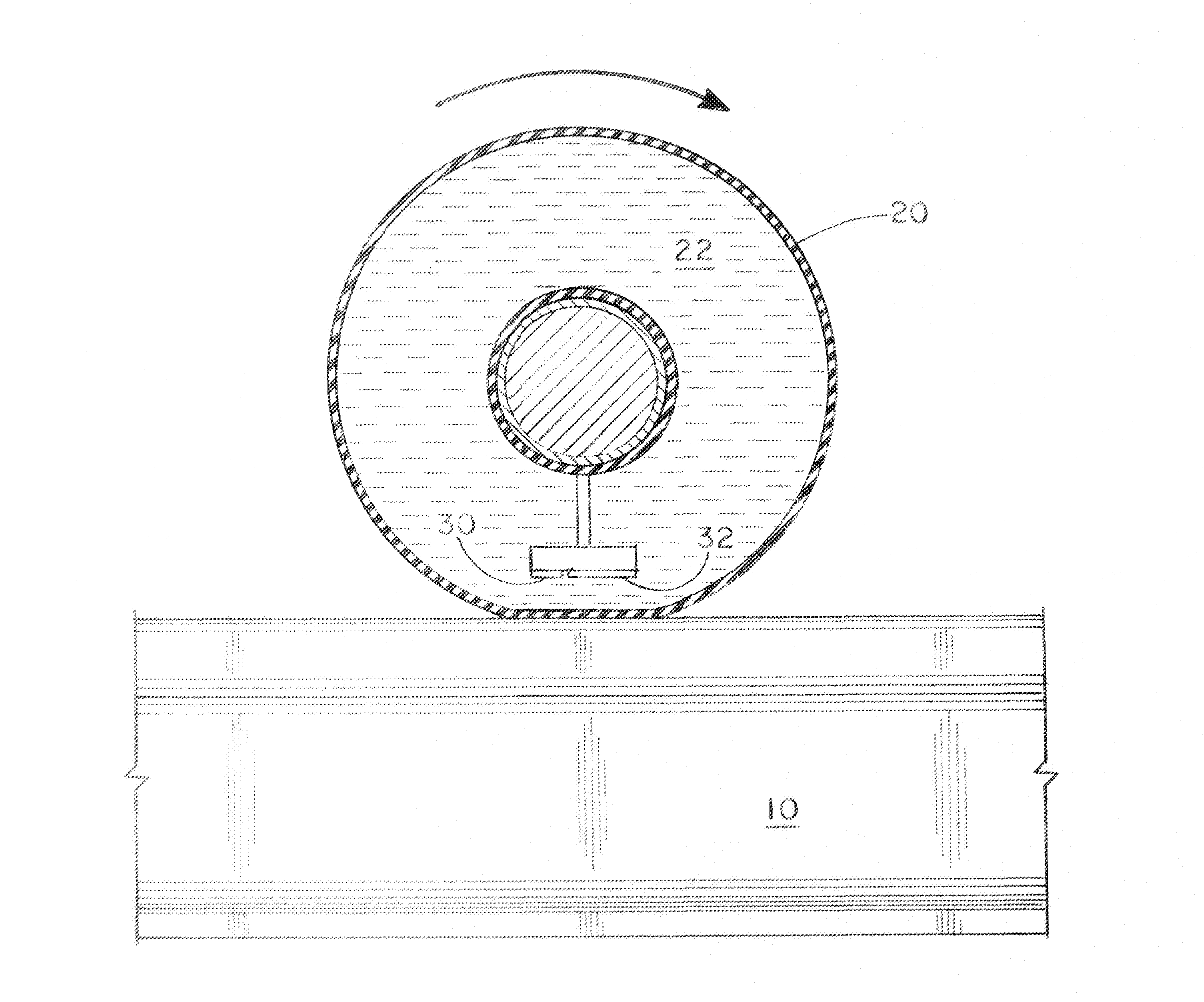
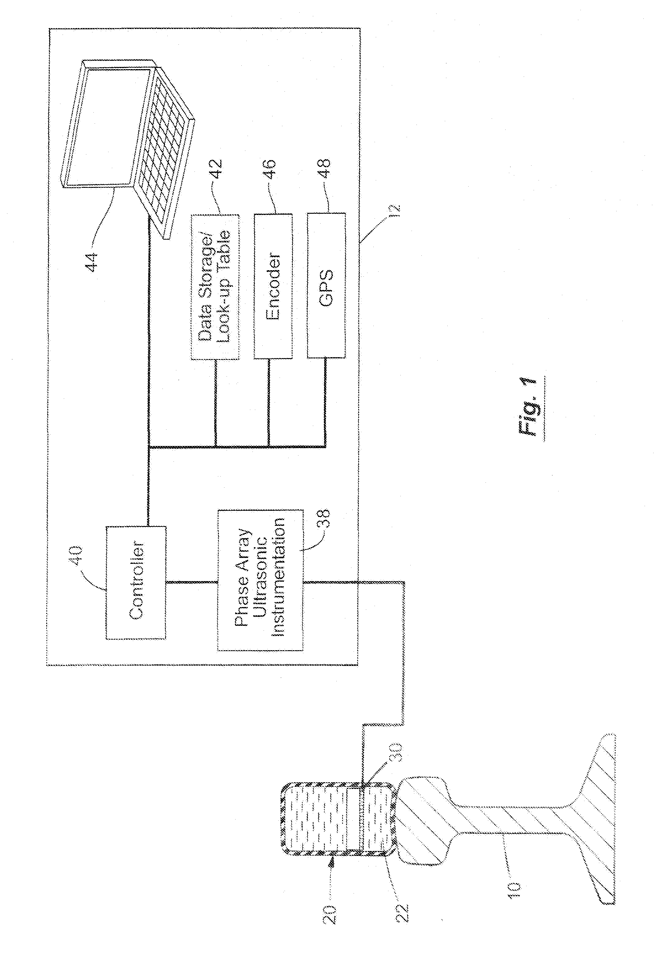
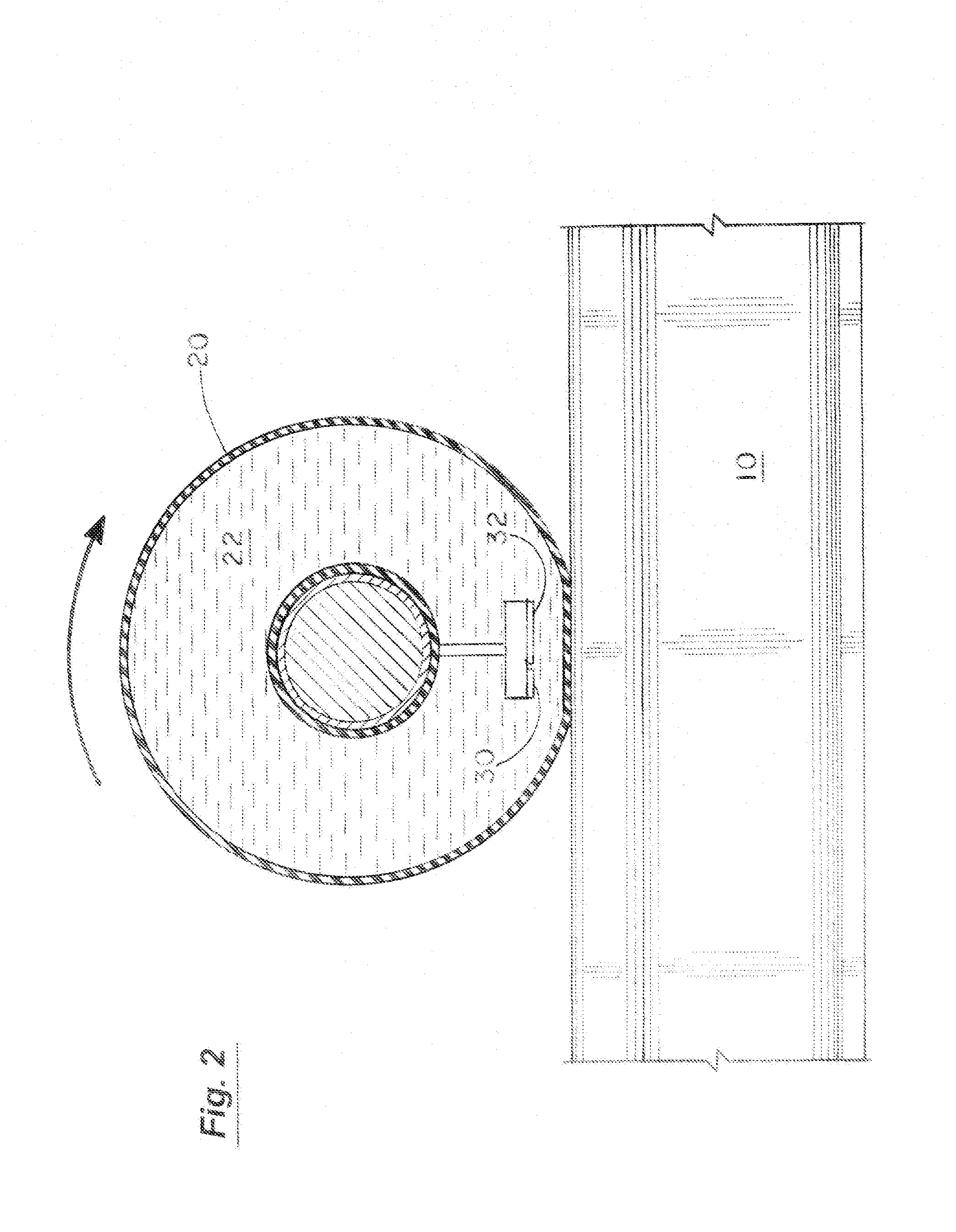
[0027]FIG. 1 is a simplified system block diagram of the present rail inspection system carried by a railway vehicle 12 to inspect a rail 10. The present ultrasonic rail inspection system is mounted on a suitable railway vehicle 12 to move along the rail 10 to be inspected. For example, a by-rail vehicle with a rear mounted carriage can be employed to carry the roller search unit (RSU) 20 containing a fluid 22. The test vehicle 12 and RSU 30 are used to guide a number of phased array ultrasonic probes 30-36 (shown in FIG. 3) along the rail 10. FIG. 2 is a cross-sectional side view of the rail 10 and RSU 20. The test vehicle 12 can also be equipped with a couplant spray system that applies a thin layer of liquid couplant onto the rail head prior to contact with the RSU 20.

[0028]Each phased array ultrasonic probe 30-36 is configured to scan an ultrasonic beam with a variable beam angle toward a section of a rail and receive an ultrasonic return signal from the rail. The phased array u...


PUM


Abstract

A system for inspecting railroad rail using phased array ultrasonic technology measures the time of flight of ultrasonic signals at locations across the rail head to determine the wear profile of the rail. The rail wear profile is then used to adjust the focal laws of the phased array ultrasonic probes to dynamically compensate for changes in the rail profile as the inspection vehicle moves along the rails.

Description

RELATED APPLICATION[0001]The present application is based on and claims priority to the Applicant's U.S. Provisional Patent Application No. 62 / 148,289, entitled “System for Inspecting Rail with Phased Array Ultrasonics,” filed on Apr. 16, 2015.BACKGROUND OF THE INVENTION[0002]1. Field of the Invention[0003]The present invention relates generally to the inspection of railway rail and more particularly to the inspection of in-situ railway rail from a moving vehicle on the track. More specifically, the present invention is in the field of phased array ultrasonic non-destructive evaluation.[0004]2. Statement of the Problem[0005]Ultrasonic nondestructive testing is a common inspection technology for detecting flaws in solid materials. Present-day ultrasonic systems for rail inspection consist of an inspection vehicle, at least one rolling search unit (RSU) per rail, multiple single-angle transducers, an ultrasonics controller and acquisition unit, and some means of processing, displaying...

Claims


Application Information

Patent Timeline
IPC IPC(8): B61K9/10G01N29/28G01N29/22G01N29/04
CPCB61K9/10G01N29/225G01N29/28G01N29/04G01N29/07G01N29/262G01N2291/0258B61L15/0072B61L23/044B61L23/045G01N29/265G01N2291/106G01N2291/2623B61L27/53G01N29/24
Inventor WITTE, MATTHEW WARDKALAY, SEMIHWELANDER, LUCAS RAHEBOULWARE, PAUL CHRISTOPHERSPENCER, ROGER LYNN
Owner TRANSPORTATION TECH CENT
Why Eureka
Try Eureka